

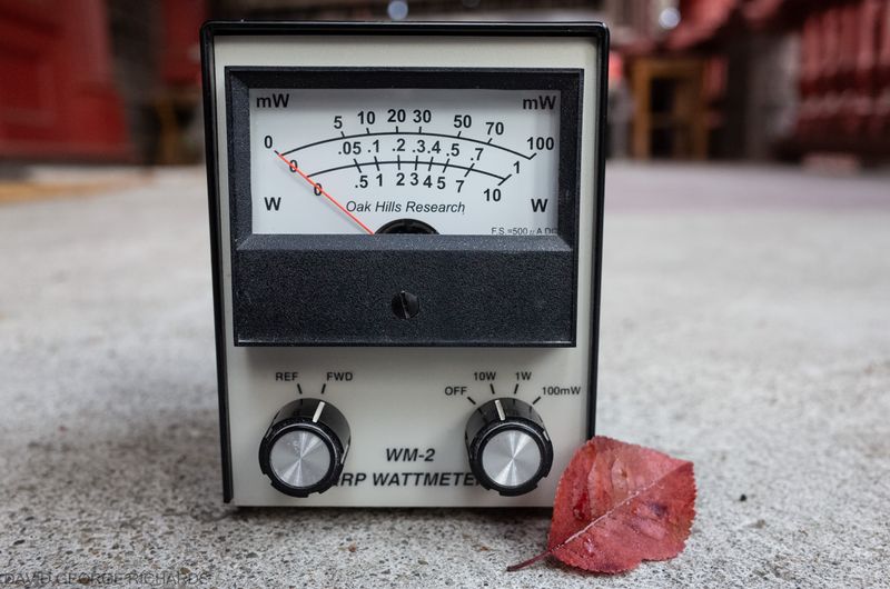
Some years ago, I purchased and assembled an Oak Hills Research WM-2 QRP Wattmeter from Milestone Technologies. As far as QRP wattmeter kits go, it was something of a classic at the time, and as such, I wanted one. I’m glad I made this purchase, as they are no longer available – at least, in this form. Another company is offering a very similar kit, but without the decals on the case. I was told that they acquired the rights to it from Milestone Technologies, so this would be appear to be a direct clone of the WM-2. The WM-2 is a great little wattmeter, with 3 ranges representing 100mW, 1W, and 10W full-scale – an ideal selection of ranges for the QRPer. You can read both forward and reflected power. While direct readout of SWR is not offered, it can be calculated from the forward and reverse power readings. The WM-2 has an analog meter and can be left inline while operating. Apart from the satisfaction of being able to see the needle bob up and down when transmitting, this type of indicator is very useful when peaking circuits for maximum output. It can certainly be done with a digital readout, but an extra stage of “translation” needs to happen in the brain, converting the number on the readout to a “level”. This process when looking at an analog meter is more immediately intuitive.


That was so many photos of my WM-2, that you might be thinking, “Hang on – isn’t this a post about the QRPoMeter? Well, it is – and we’ll get to that very soon. I don’t think I ever blogged about the WM-2 when I built mine years ago, so felt it was time to give it some air time on my blog.
For my purposes, the WM-2 meets my needs. However, I don’t have any other instruments with which to check the accuracy of it’s readings. A Bird wattmeter would be nice, but the expenditure is hard to justify. Another option is to use an oscilloscope to measure the peak to peak voltage a transmitter develops across a 50 ohm dummy load, and use that to calculate power. This is a definite possibility in the future, as I do intend to add a digital storage oscilloscope to the shack at some point. In the meantime, it would be good just to have another wattmeter of similar accuracy, simply to increase my confidence in the readings I am getting from either one. For the kind of operating us QRPers do, absolute accuracy is not essential. 5% of full scale is good enough which, on a 10W scale, means ±0.5W. If I claim to be transmitting with 5W, then the difference between 4.5 and 5.5 W is unlikely to even be noticed at the receiving end.
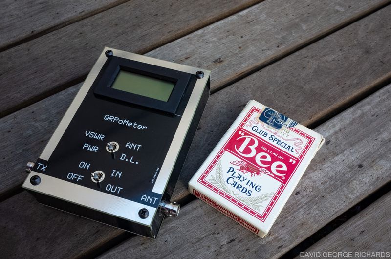
The QRPoMeter, designed by Dave Cripe NM0S, has been on my radar for a very long time. Originally offered by the 4SQRP group, it is a very affordable instrument for measuring power and SWR. It has a built-in dummy load, to make measuring the power into a 50 ohm load an easy task. Also, when measuring SWR, it uses a resistive bridge, so that the maximum SWR your transmitter will see is 2:1. I’ve long wanted to assemble this kit. A few times, I’ve waited too long to purchase a kit, only to find that it was no longer available (the SST, once offered by Wilderness Radio, was one example). With that in mind, and also because the QRPoMeter is so reasonably priced, I went ahead and placed an order with NM0S Electronics.
A few days later it arrived, in a small flat rate Priority Mail box. I love getting radio parts and kits in the mail. It’s exciting! The PCB pieces that, as well as forming the circuit board, also comprise the case, were slipped in between pages of the assembly manual to protect them. There was also a little bag of goodies. I love little bags of radio parts!
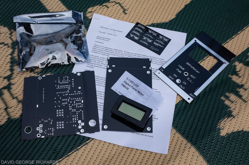
The bag of parts, emptied out into a styrofoam tray –

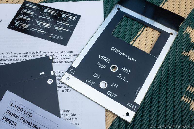
Also included was a piece of thin 2″ x 3.5″ PCB material, etched and silkscreened on both sides. On one side was the business card of NM0S Electronics. On the other side were these handy little band plans –

The pieces that form the sides of the case have to be broken off from the larger pieces of PCB material, and given a very light filing to remove the rough edges. It was immediately obvious how smart the final product was going to look. It was raining very, very lightly when I took this photo. If you look carefully, you might see some very small raindrops on the panels –
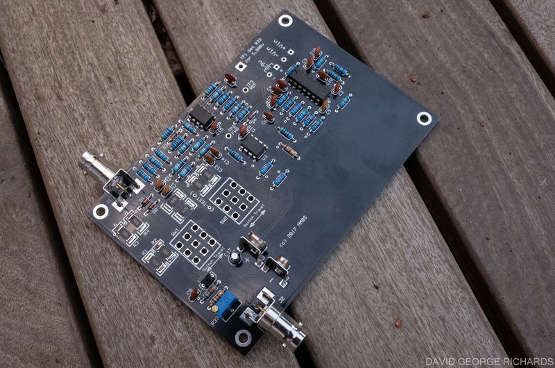
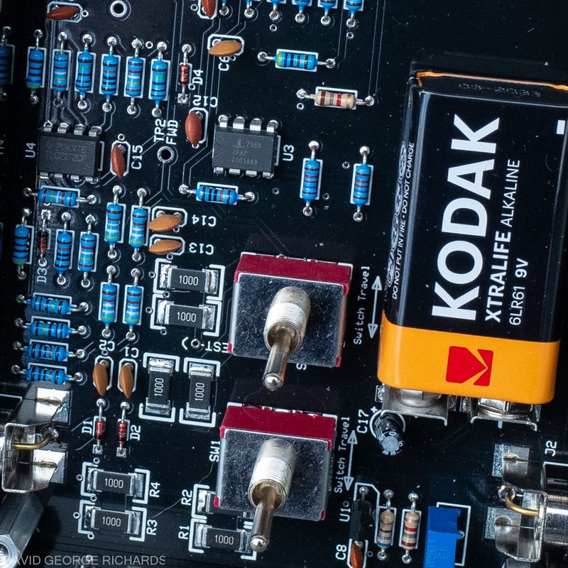
For anyone who has assembled a few kits, construction is uncomplicated. Dave’s instructions are clear and straightforward, consisting mainly of a checklist for populating the board, and instructions for constructing the included PCB case. The switches and input/output BNC connectors are all mounted directly on the board. The only wiring required is a 4-conductor ribbon cable that is used for the connections between the board and the LCD panel meter. Other than wiring up this meter, and soldering the case pieces together, construction of the QRPoMeter consists of populating the single PCB with the parts. This picture is of the finished board before the two switches were installed –
I only discovered two very slight issues during assembly. Neither will present a problem for anyone with a little experience, but they might slightly confuse a beginner. These were due to a change in sourcing parts, and Dave said he will take care of them in future versions of the construction manual. These were –
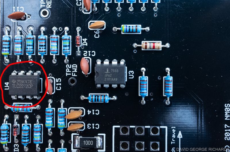
- U4, the TLC2272, had no dot or u-shaped indentation to denote the correct orientation. I used the printing of the device number on the top of the IC as a guide instead, and this turned out to be right. See picture below, with U4 circled in red –
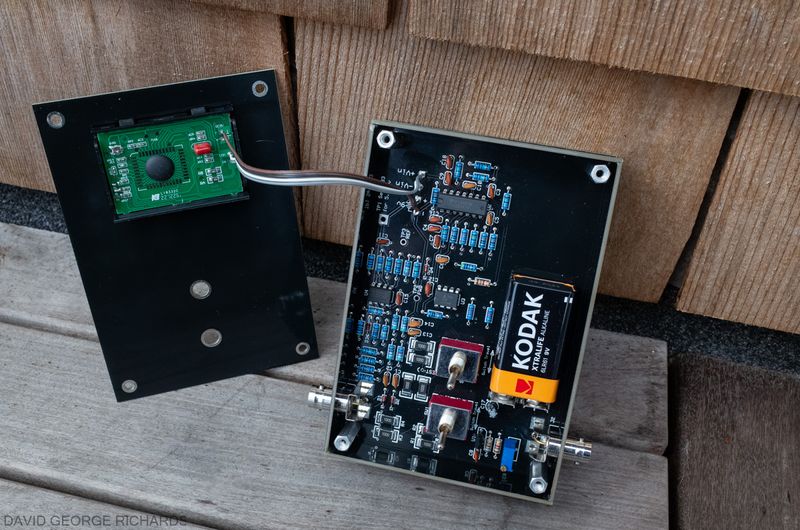
2. When using the 4-conductor ribbon cable to connect the LCD panel meter to the board, because the instructions refer to an earlier version of the meter, a beginner might experience some uncertainty as to which holes on the meter board to connect to which holes on the main board. On the main board, there are two pads next to each other marked +Vin and -Vin. These are connected to the pads on the meter board that are marked “IN” and “COM” respectively. The other two connections are more obvious. The pads on the main board, next to the schematic symbol for a 9V battery, marked + and -, are connected to the pads on the back of the meter board, next to the “DC 9V” text, that are marked + and respectively.
A portion of the board in greater detail, showing the 8 large surface mount resistors that form the dummy load/resistive bridge (or, to be more accurate, 7 of them, and a small part of the remaining one) –
Calibration is straightforward, and requires a fairly accurate DMM. I used my Brymen BM235 (the EEV Blog version). The only other piece of equipment needed is any HF QRP transmitter with an output of between 2 and 10 watts. The output power doesn’t need to be known, as long as it falls within that range. When the unit is calibrated, you have a very handsome and useful piece of QRP kit!


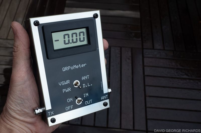
The QRPoMeter seems to be accurate enough for my purposes. Power measurements are in line with the ones reported by my WM-2, taking into account the accuracies of both instruments. SWR measurements are similar at the lower readings. They differ by fairly large amounts at higher SWR’s. This doesn’t concern me though, as once the SWR goes much above 2 or 3:1, it’s exact value is of little interest to me. I just know that I want to get it back down below 2:1! A useful feature of the resistive bridge in the QRPoMeter that is used to measure the values of forward and reflected power, is that when SWR is being measured, the transmitter never sees an SWR higher than 2:1. This was verified with the SWR indicator in my Elecraft K2.
Thanks Dave. A good-looking and worthy little piece of QRP test gear! The QRPoMeter is available from NM0S Electronics.

You have to install four surface mount resistors. Don’t panic; they’re huge and easy to solder. (The 4SQRP version used through-hole parts but those are no longer readily available with the necessary specs.) There is also a surface mount IC under the blob on the display board, but that board is completely assembled when you get the kit. All in all it’s an easy kit to build; I worried a bit about soldering the joints that hold together the case, but NM0S designed the case well so you don’t need huge amounts of heat for those, like you do for a PCB case that is made from unetched boards.
Something that confused me when I built mine is that in the SWR mode, the meter will continuously count up if the meter is idle. You have to apply RF to get it to behave normally. The manual does not explain that.
I did not have a quality instrument for measuring QRP power levels until I got the QRPometer. I’m glad I have it now. Another endorsement: Hans Summers uses it to measure the power output of the assembled QRP radios that QRP Labs sells. He mentioned it once in passing; I think it was on the groups.io list for QRP Labs.
Thank you for mentioning the surface mount resistors Shirley! I just amended the post to include a shot of them (mine has 8). Good points about the PCB case. When I’ve made cases from pieces of PCB material, I’ve had to compensate, to account for the fact that 90 degree angles tend to become 89 degree angles after the solder cools and shrinks. Dave’s case design avoids having to perform any of these slightly more tricky maneuvers.
Talking of the meter count creeping upwards, I have found that when measuring power, my QRPoMeter slowly creeps up for 10 or 20 seconds before settling on a final reading. However, the reading is easily “close enough” after a few seconds.
Cheers, and 73 for now,
Dave
AA7EE
Well done you!! This looks like fun. use my Elecraft W1 kit often (just completed a QCX+ and the W1 helped verify the QCX+ works). I miss your construction projects. Hope to see more posts in 2024. Paul W6PNG
Hans’ kits are such great value for money Paul – a high level of performance for minimal outlay. Great stuff – and I have no doubt you’ll be using it to work some great DX!
73 for now,
Dave
AA7EE
Hi Dave !
Great review of a very useful QRP accessory. The fact that the TX never sees an SWR higher than 2 to 1 is a bonus and the price is certainly more than reasonable. I definitely plan to get one in the future. Dave also has very interesting QRP transceiver kits and other items available on his website.
Thanks Dave !
Jim WB4ILP
Jim – Dave’s offering of the Norcal 40B is *very* tempting. I think it was a great move for him to make this kit available again. Likewise, his Cricket line of simple rigs are a great option for anyone who wants Pixie-like simplicity, but with better performance.
73 for now!
Dave
AA7EE
Hi Dave,
Yes the NorCal 40B does look like a nice kit and a great radio. I think it may be on my wish list. Also, the Cricket looks like fun.
I was reading some emails on the GQRP group today regarding the WM-2 and Oak Hills Research. OHR was purchased by Dennis, N1IMW and it will be reopening possibly by years end. Rex W1REX (QRPme) is laying out a new board for the WM-2 so it looks like that fine instrument will live on. That’s good news.
Jim
That’s interesting news Jim – thank you for sharing. It will be interesting to see an updated version of the WM-2 and, or course, to see the newly revived OHR. I’m waiting with interest!
Dave
AA7EE
Thanks Dave for the write up and tip on the qrp-O-meter. I bought and assembled one based on your post and it works great.
p.s. AM1700 in San Francisco is QRT. I guess I scratched the broadcasting itch sufficiently. Although, I kept all of the equipment in case I suffer a relapse.
73, Matt
Glad to hear that you’re happy with the QRPoMeter Matt. My Part 15 went the same way as yours. I also have hung onto all the hardware. Maybe one day I’ll have a living situation where I can install a ground-mounted transmitter with an extensive radial system, to see what these Rangemasters are really capable of! Your signal was well-modulated, by the way.
73 for now,
Dave
AA7EE