

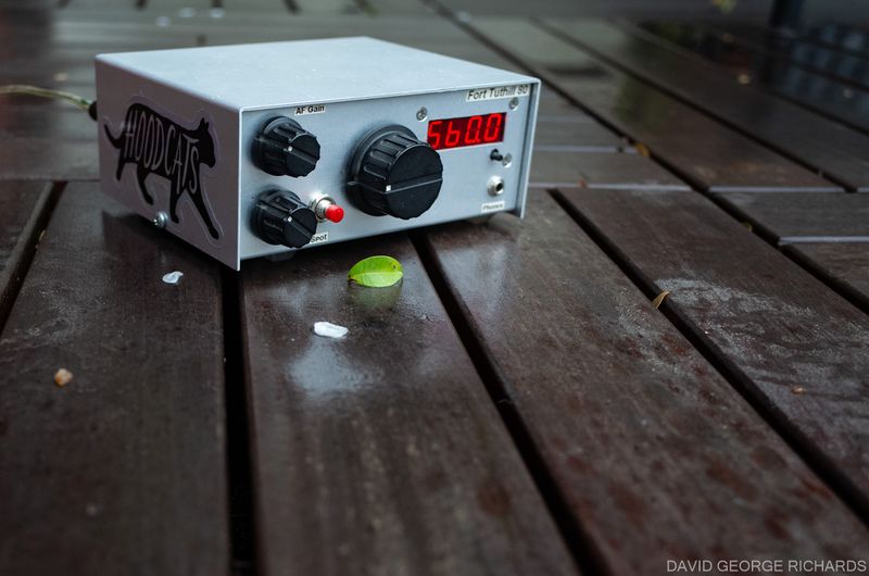
Back in 2009/2010 the Arizona QRP Scorpions released a little kit designed by Dan N7VE, called the Fort Tuthill 80. It was a QRP CW transceiver, with a direct conversion receiver and a transmitter capable of putting out about 3W. It caught my imagination, and I just had to build it. I have never had a great antenna for 80, and don’t operate on that band a lot, but one of my successes with the Tut 80, was a QSO with the T32C DXpedition team in Kiritimati. I was running 3W from the Tut80 into a 40M coax-fed dipole! This made the QSO feel like a great victory.
The first run of Tut 80 kits was over fairly swiftly. This run was, I think, either 100 or, at the most, 200 kits. There was talk of another run, but it never materialized. Doug Hendricks began selling kits of the design for 160M and 15M through his QRP Kits website. Ownership of QRP Kits has now changed, and both Fort Tuthill kits have been retired. In other words, like a lot of QRP kit rigs of that era, if you have one, you are sitting on a limited edition classic!
I have never used my Tut 80 a lot, though every now and again it comes down off the shelf for a jaunt around the lower end of 80. There used to be a Yahoo Group for Tut 80 builders. Sadly, that wonderful repository of information on so many subjects was all lost several years ago when the plug was pulled on Yahoo Groups. One of those valuable bits of info was a post by noted QRPer Cam Hartford N6GA (now sadly, SK). He had modified his Tut 80 for varactor tuning, which struck me as a very desirable mod. The stock polyvaricon, though serviceable, didn’t make for the best user experience, in my opinion. The polyvaricon is just a little “spongy” in feel, making precise spotting a bit tricky at times. Also, I had added the suggested toggle switch to separate the tuning into two bands. It switched in an extra NPO capacitor for the lower band. Although it worked, I didn’t love the idea of using a toggle switch in a frequency determining circuit. Cam’s varactor mod had been on my mental list of things to do for years.
Several times over the years, I have come close to performing this mod, but never quite found the necessary mojo. Then, very recently, inspiration struck, the rig came down from the shelf, the Bournes 10-turn 10K pot that had been stashed in my parts drawer for a rainy day was retrieved from the parts drawer, and I got to work.
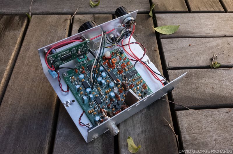
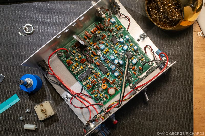
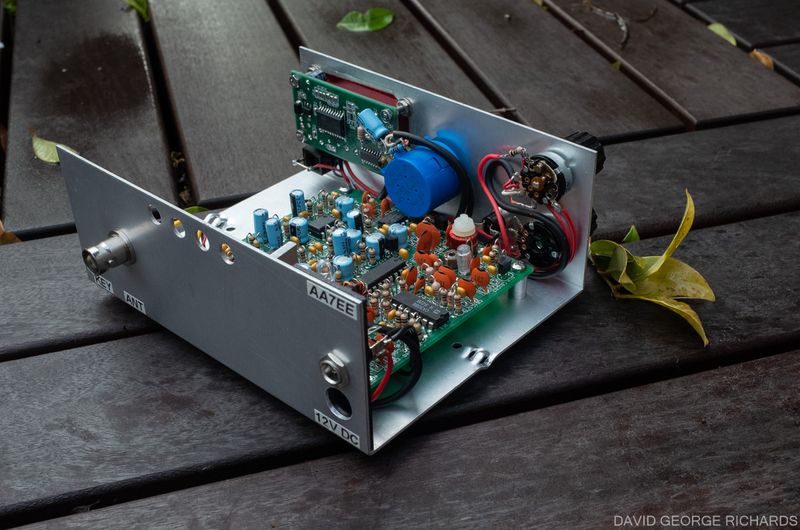
A side-benefit of making the decision to do this was that, in the process, I could tidy up the wiring a bit. At the time I assembled the Tut 80, my soldering was already good, but I had not yet become quite as focused on making the wiring to the boards in my projects quite as tidy. This photo of the Tut 80 before the modifications makes my point. Not a huge mess, but it could use some improvement. This picture was taken in 2010, when I had just finished building my Tut 80 –
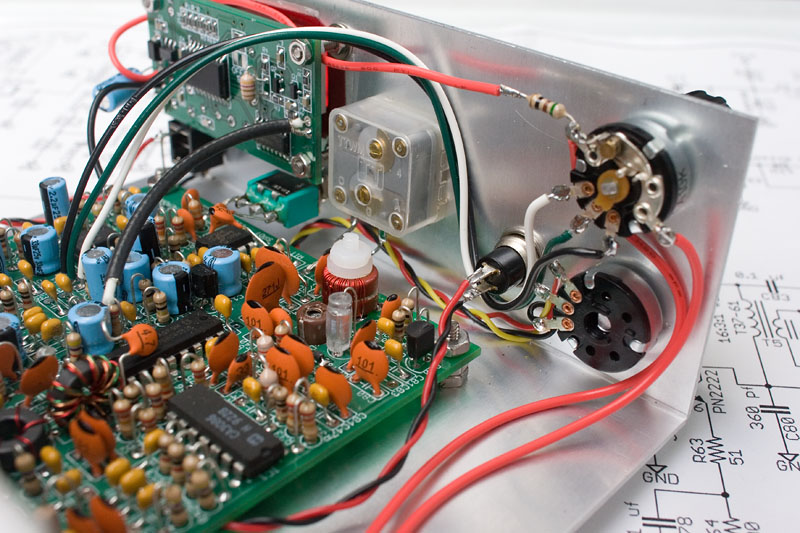
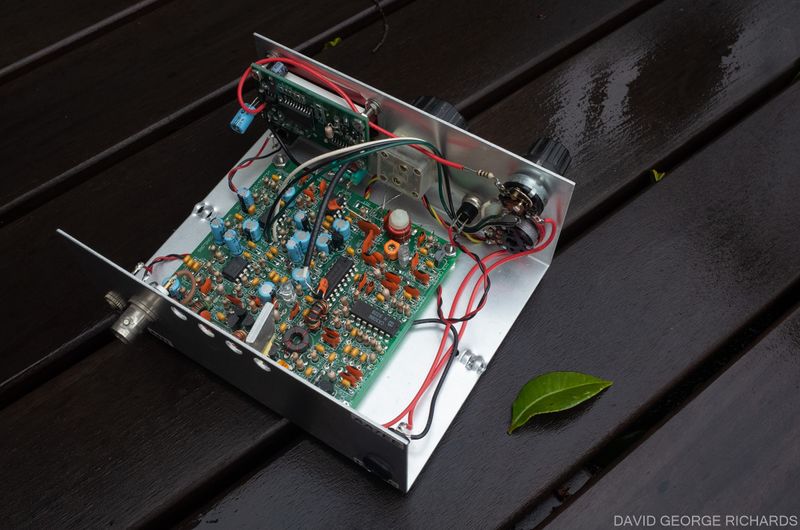
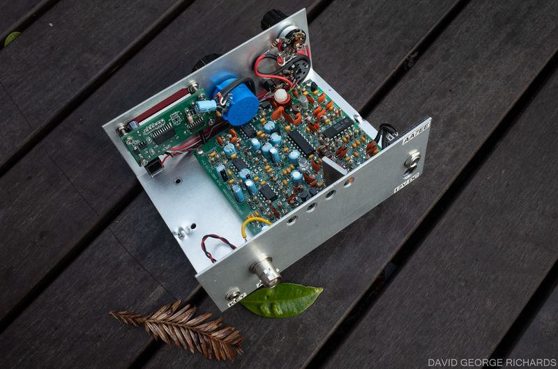
The next few pictures were taken recently, just before the mods were performed. This wiring needs to be tidied up! –
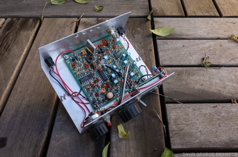
The “Hi Lo” toggle switch in the above picture will be removed, as there will be no need for it. No idea what I will do with the hole.
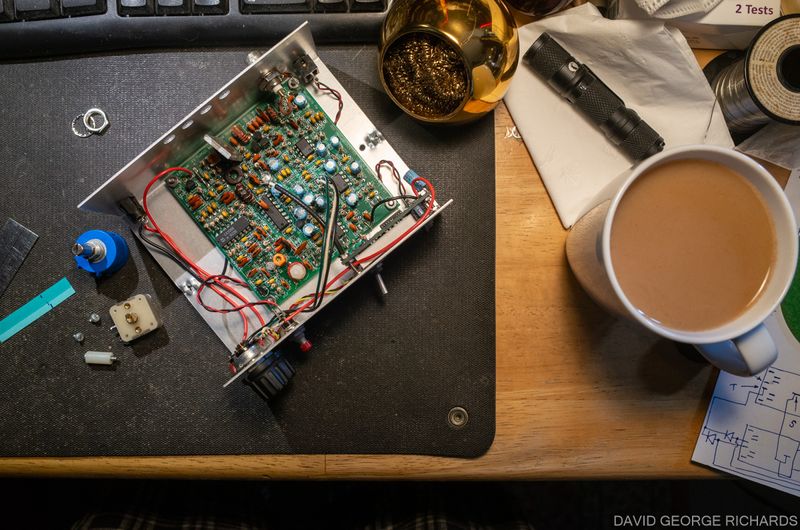
The rig on my desk, with the polyvaricon and 10-turn pot getting ready to swap places. The 10-turn pot is made by Bourns. They are not cheap, but they are quality pieces. The part # is 3590S-2-103L –
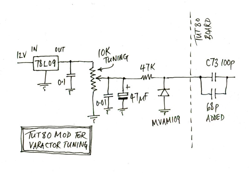
Here is the schematic of Cam’s mod, as drawn by him, and posted to the Tut 80 Yahoo Group –

And here is what he wrote about it –
Sorry about the pencil/paper rendering. All of the parts came from my inventory. The MVAM108 was left over from another project, probably a 2NXX. The ten-turn pot came from a swap meet. It’s a Bourns 100K unit, but the value is not critical. A 50K or 10K would probably do as well. For starters, I did this more than ten minutes ago so short-term memory vacancy has taken it’s toll. I reverse-engineered the schematic but can’t really remember the why of some of the decisions. Lots of trial and error, no real science involved. It works, however. The radio covers the bottom 100 KHz of 80 meters almost exactly. As far as linearity is concerned, the first turn at the bottom of the band yields 6 KHz, this increases to about 13 KHz in the middle of the band, then drops back down to 6 KHz at the top end. So it tunes faster mid-band but is still vastly better than 100 KHz in one turn. I added a digital dial so the linearity really isn’t an issue. And it retains the stability of the original design, which is to say, like a rock. I’m thinking that the on-board regulated 5 volts didn’t give me enough band spread so I went to a little 3-terminal 78L09 9 volt regulator. I mounted this Manhattan-style on a little scrap piece of pc board and mounted it in an available corner of the box. The rest of the pieces soldered directly to the terminals of the 10-turn pot. The lead from the varactor soldered to the hole in the board that was vacated by the polyvaricon. In looking at the board now I see a couple other caps that I added to fine tune the frequency range. I tack-soldered a 33 pF NPO cap across C73, as I’ve noted on the hand-drawn schematic. This was probably the cap that was supplied with the kit for location C83. The notation on the original schematic says “C83 optional, use if needed.” In that location I used a 47pF NPO from my collection. The changes I made were necessary to accommodate the parts I had on hand, so the usual disclaimers apply. Caveat emptor, YMMV etc. It’s a fun bit to play with, IMHO.
72, Cam
N6GA
I had an MVAM108, though it was an unmarked part, and I didn’t completely trust the source. I could have tested it, but I had some MVAM109’s from Kits and Parts, so decided to use one of those instead. Here is my version of Cam’s mod. My values are a little different, and I have added one part –
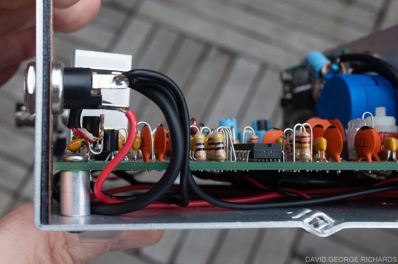
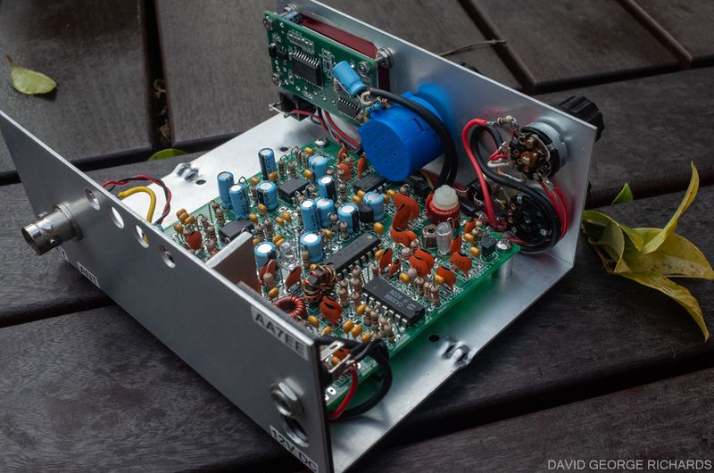
The 78L09 regulator was mounted at the back of the board, next to the existing 5V regulator IC. The input and ground legs of the part were poked through the holes in the board for 12V power and ground respectively. The 9v regulated output leg was bent up away from the board. The next two pictures may help to make it a bit clearer. The existing 5V regulator, the 78L05, is the one furthest away from the back of the enclosure (i.e. closest to the CA3086 IC). Also, in this picture, you will see that I moved the 12V DC input power connector higher up the rear of the enclosure. This was to avoid fouling the board, which had been moved. A small piece of PCB material blocks the old hole, and is held in place by the new connector –
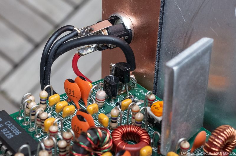
In the next picture, you can see how the cable (lavalier mic cable, incidentally) that carries the regulated 9V supply to the rest of the tuning circuit is soldered to the bent-up output leg of the 78L09. You can also see the little 0.1µF bypass cap that connects from the output of the 78L05 to ground –
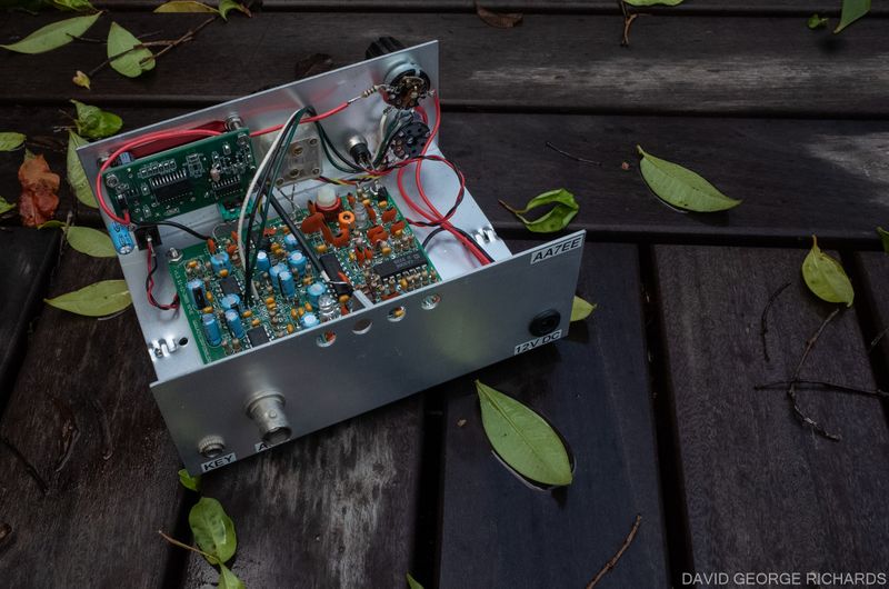
The MVAM109 varactor was mounted on the board, into the two holes marked “Tune” that had previously been used to connect to the main tuning polyvaricon. It is circled in red in this picture –
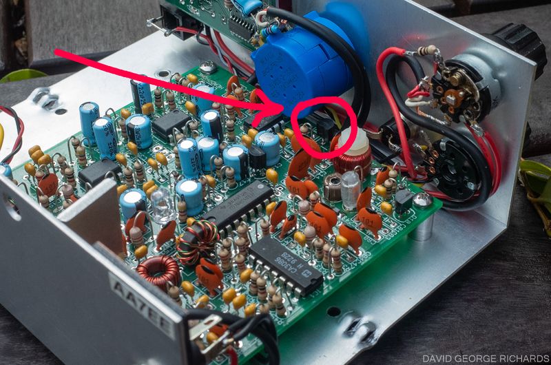
With the MVAM109, I found that a 68pF NPO cap across C73 gave me coverage from 3487 to 3615 KHz. In retrospect, I am not entirely sure why I used a 68pF cap at that point. The shorter and much less convoluted version of the story is that, by the time I had soldered that cap to the bottom of the board, I was past the point of wanting to fine tune the coverage. I figured that having that extra cap in parallel with C73 could only help the long-term stability, by spreading any heating effect over two capacitors instead of one, so I left it there. The reason I didn’t adjust trimcap C82 (which is on the main Tut 80 board and not shown in any schematic here) to bring the coverage higher, is that it was already at minimum capacitance. Perhaps one day I will further fiddle with the capacitance values to bring the coverage more in line with my ideal of ~3495-3585 KHz but tuning with the 10-turn pot is already a massive improvement over the half-turn with the polyvaricon, so I’m not bothered. The 10-turn pot has a much lower friction and smoother feel, in addition to the fact that it covers the tuning range in 10 whole turns.
The 47µF capacitor between the slider of the 10K tuning pot and ground was added to remove the slight “whizzing” sound that occurs in the headphones when a wirewound pot is used for varactor tuning. If your pot has a carbon track, you don’t need this part. In fact, the whizzing sound is so faint that 80M band noise usually covers it, but I like to add that capacitor anyway.
Another mod that piqued my curiosity was one posted by Dan N7VE. He had modeled some changes to the PA to make it more efficient and put out more power. Although at the time, he hadn’t tried it, he felt sure it would work. I found mention of it online by someone who did the mod and found that, as a result, his Tut 80 put out 4.5W. Here is the description of N7VE’s PA mod, in his own words, as posted to the now-defunct Yahoo Group –
Tut 80 PA Mod for Class D
The more efficient output network that I have simulated involves:
1) Changing L4 from 24 turns to 19 turns
2) Shorting out C58 so that C57 and C59 together provide 2000 pF of C at
that point rather than the current 1500 pf.
3) Replacing L6 (a FT37-43 core) with a T37-2 core with 22 turns. There
is no tap on this new coil. The coil end points go to pad 1 and pad 2.
Pad 3, where the tap used to go, is shorted to pad 2.
This simulates well to give a non-critical, class E type output, even
though it is being driven with a less than optimum sine wave input. The
output would be somewhere in the 4.5w range.
I want to test this when I get back, but someone could try this if they
wanted to see how it does. I think this would take unwanted heat and
change it into extra output power, allowing the finals to run cooler
than they currently do.
– Dan, N7VE
I made the above mods to the PA, and my Tut 80 now puts out 4W instead of 3W. Score!
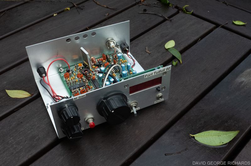
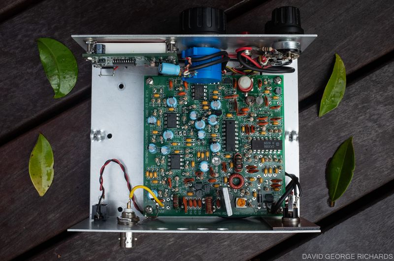
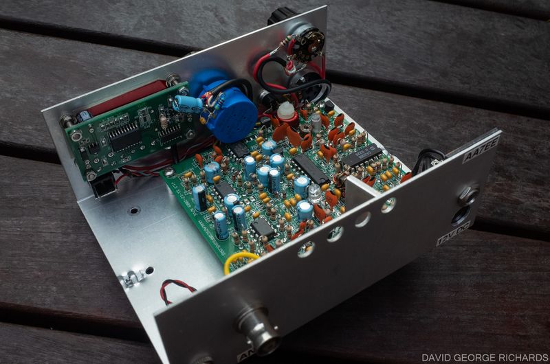
The final task to accomplish was to tidy up the wiring a bit. This was accomplished by connecting all the wiring to the underside of the board, and running it underneath the board. Shielded cable was used to connect the AF gain pot to the board. Shielded cable wasn’t really necessary, but the stuff that is intended for lavalier mics is thin and flexible, and works well for this purpose. I use Mogami W2697. The twisted wires for the key and headphone sockets were scavenged from a multi-conductor cable. The feed from the board to the KD1JV Digital Dial is RG174/U. You can’t see it in the pictures, as it is hidden quite well. I think you’ll agree that it looks tidier inside the enclosure now –
My little Tut 80 now had nicer tuning and more power out, but what about the stability of the VFO? I ran a series of tests, from a few hours long, to one that was 36 hours in total. All the tests gave very similar results. At 3560KHz, from a cold start, it drifted steadily downwards about 260Hz in the first 30 mins, and a total of about 300Hz in the first hour. Thereafter, it didn’t drift more than ±30Hz for the next 10 hours. Most of that time, it didn’t drift more than 10Hz in an hour. In the one very long test, that lasted for 36 hours, after 10 hours of holding relatively steady, it began a new steady downward drift, reaching a maximum excursion of an extra 270Hz from the frequency it was at 1 hour after the cold start. Nearly all of this extra drift was steady though, and for most of this time, drift was no more than 10 or 20 Hz in an hour. This level of drift is good enough for the type of operating I do with my Tut 80.
Well, I rather wish I’d had a brand new exciting build to share with you, but that’s not how things have been going here at the AA7EE radio ranch recently. I figured that there might be a few Tut 80 owners who would be interested in these mods and, as the Tut 80 Yahoo Group no longer exists, decided to share them here. It it helps one person, my mission has been accomplished. FYI, the manuals, including schematics, for the 160 and 15M versions of this rig are hosted in the “Retired Kits” section of this site. For anyone who needs a copy of the assembly manual for the original Tut 80, drop me a line. My email address is good on QRZ.
Cam N6GA and I exchanged friendly emails some years ago. He had family in Oakland, and talked of visiting when he was next up here. I do wish he were still around, so I could say – hey Cam. I tried your Tut 80 varactor mod, and it works like a champ!


Nice mod Dave and a good tidy up too. I’ve used the Bourns 10 turns in combination with a varactor for VFO tuning on one of my home brew designs and I went through 3 before abandoning them for a more expensive brand. They were failing with intermittent track contacts at the main usage point (which equated to 7.030MHz on my 40m rig). This caused the VFO to hop around all over the shop. Most annoying. Keep an eye on that and I hope you have better luck with them than I did.
Mark
That’s interesting Mark. I have used these Bourns pots in several little rigs, with no issues so far. However, if there’s a higher quality part available, I’m interested. Which brand are you using?
Dave
Extremely well documented Dave – as it always is.
Thanks Tony. In fact, you reminded me of a detail I had left out – where I mounted the varactor. I just added another photo with a brief description. One of the great wonders of the internet – posts can be edited at will. I am still finding errors in 10 year-old articles and correcting them!
Wonderful to hear from you. I am listening to your QSO Today podcast interview as we speak.
Dave
AA7EE