
There are two Tuts in the San Francisco Bay Area that I know of – The King Tut Exhibition currently showing at The De Young Museum in San Francisco, and The Fort Tuthill 80 in my apartment in Oakland. It’s been a longish road gettting this little direct converison transceiver completed, mainly due to the fact that I originally housed it in a larger case with a vernier dial before deciding against it and rehousing it in a smaller case without the vernier.
As I’ve mentioned before, the Fort Tuthill 80 is an 80M direct conversion CW transceiver designed by Dan Tayloe N7VE, who has spent a lot of time thinking about distributed filtering in direct conversion receivers, and it shows in the performance of this little radio. If this the first time you’ve come across this radio, the Yahoo Group will give you a lot of info. The AZ ScQRPions have the rights to produce the 80 meter version, and then Hendricks QRP Kits will be selling versions for other bands.
The first part of the build was covered in this post. I wasn’t too sure about what I thought would be the tricky tuning that may result from coverage of something like 50KHz of band in just a half turn of the knob. That was equivalent to 100KHz a turn, so my thoughts turned to fitting the rig with a reduction drive. Dan advised me to try it without the vernier first, as he had used a vernier before, and felt it unnecessary. I was convinced that a vernier was the way to go though, and this was it looked like in the case before fitting the frequency readout:
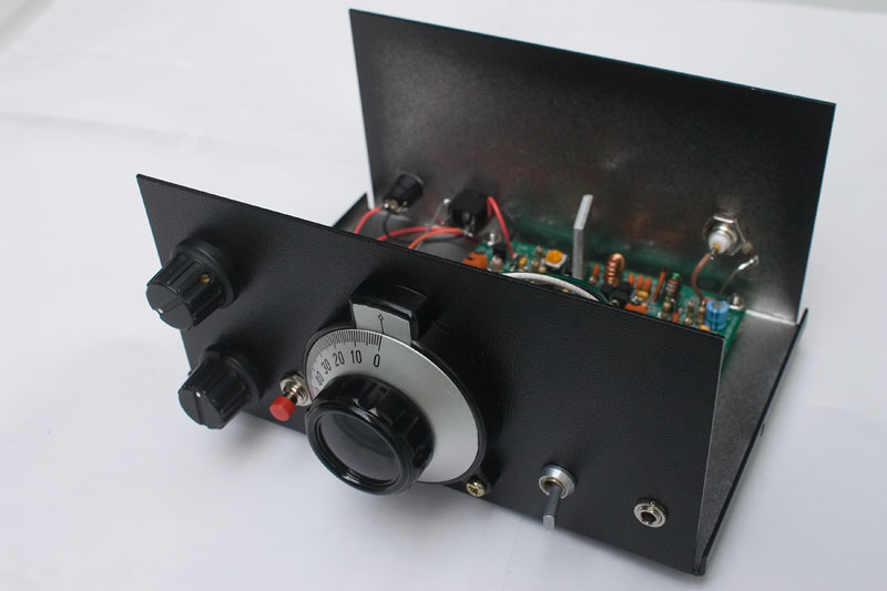
I was pretty excited about the prospect of this with a digital frequency readout and yellow decals, but after a few days playing around with it, I decided that I didn’t like the vernier. Dan didn’t mention why he hadn’t been keen on the vernier, but my experience was that the advantage of the 8:1 reduction was negated by the stiff feel to the tuning – precisely tuning a signal wasn’t as easy as I was expecting.
Folk in the Yahoo Group had been talking about fabricating cases from PCB materials. There’s a really good tutorial on how to fabricate a case from PCB material written by Ken WA4MNT. You can find it in the files section of the Yahoo Group for the Tut 80. I’ve used this method for constructing VFO enclosures in the past, but never for a case to house a whole project. In retrospect, this really is the way to go; the rigidity I would have gained from using this type of enclosure would have helped the short-term frequency stability, though it’s pretty good with the case I ended up using.
Terry WA0ITP mentioned the Ten-Tec case TP-41 as a possible enclosure. John AE5X used one for his Tut80, commenting that it was perfectly sized for the radio, so I decided to order one in unfinished aluminum. I ordered 3 to meet their minimum order price of $15, so if anyone in the Bay Area wants to buy one or two of these from me, just drop me a line.
Here’s the case with most of the front panel controls installed. I also fitted a red gel to the cutout for the frequency readout to improve readability:

and here’s the same case from the front:
 A quick word about that rectangular cutout for the frequency readout because I know that some folk are put off by the prospect of cutting square or rectangular holes. The way I do it is by first punching or drilling a series of holes approx 1/4″ in diameter around the perimeter of the cutout to remove the bulk of the material. I then finish it off with a set of fine jewelers files. To make the round holes, for my entire home-brewing career until now (a span of some 30 years) I would use a hand drill, and enlarge if necessary with an old screwdriver used as a reamer. Burrs would be carefully removed with a file. This method works, but can be time consuming, and doesn’t give as clean results as using a hand punch. A trip to Harbor Freight yielded this. I got the one with the imperial-sized dies – a set of both would be great. Making round holes with a hand punch like this gives a nice clean hole with no burrs – and in less time too. It makes the whole process of preparing a case for a homebrew project all the more enjoyable. If you plan on embarking on at least a few more projects like this, owning a hand punch like this will make your life easier, and give better results.
Paradise – a soldering iron, a cup of coffee and a project to work on. What more could a guy want?
 With the rig finished, here are a few views:
 You can see the 4 vent holes punched at the rear of the chassis just above the heat sink for the finals. This particular way of doing it was suggested by Terry WA0ITP. One extra bonus to having vent holes is that you can peek through them and see the cool blue LED that Dan put in the circuit to act as a low cost shunt voltage regulator 🙂
Note that although the radio is shown tuned to 3560, the 80M QRP frequency, if anyone called me on 3560 I wouldn’t be able to hear them. This design utilizes a direct conversion receiver, so the station calling me would be at zero beat. The RIT gets you around that nicely however. I tuned the radio to 3560 for the “photo-op”, but when I monitor 3560, the readout shows 3560.5 as I like a 500Hz side-tone.
In the next view you can see the nylon nut, bolt and washer that I used to hold the VFO coil firmly to the board, to help make the VFO less prone to changing frequency when knocked. It’s not too apparent in this picture, but I used short stout leads to connect the polyvaricon to the board, also in the interest of VFO stability:
 A view from the rear:
 and finally, the regular view with the top on:
 The toggle switch just to the right of the main tuning knob is a suggestion of Dan’s that was included in the construction manual. It switches in a 27pF NPO capacitor to give an extra range of tuning allowing the rig to cover approximately 90Khz of the band in two ranges, so that the tuning rate doesn’t get too coarse. On this radio my tuning ranges are 35492 – 3547 and 3532 – 3589, giving me coverage of the bottom 89Khz of 80 meters in two tuning ranges.
The transmitted signal sounds great – nice sounding keying with no chirp or key clicks whatsoever; the transmitter doesn’t have that “homebuilt” sound! The real reason you want to build and use this rig though is because of the receiver. The filtering makes it a really nice receiver to listen to; the design includes a 3 stage 7 pole 700 Hz low pass filter. There is also filtering to reduce mains hum – a common complaint with direct conversion receivers. As a result, with the transceiver fully cased up, I cannot hear any hum at all, even with the volume fully up. The other issue that occurs with DC receivers is that of microphony, and though it does occur with this receiver, it is minimal and doesn’t impede enjoyment of the radio at all.
At this point, I’ve had no QSO’s with it, but that has nothing to do with the rig. It has more to do with my marginal antenna for 80 meters (to be improved soon hopefully), the fact that I’ve been busy building and casing it as opposed to being on the air with it, and also the fact that I get a great deal of local QRN on 80 in the evening, making it hard to use without a noise blanker. If I can improve my antenna system on 80, then I’m sure that some early morning starts will net me QSO’s in the very early morning when 80 is still “happening” and the local QRN isn’t there.
Of course, homebuilt projects are rarely complete. I’m not sure if I’m even going to bother with painting the case and putting decals on it, as I kind of like the way it looks now, but I’d like to improve the rigidity of this low-cost Ten-Tec case with a couple of struts between the front and rear panels at the left-top and right top of the case. I’d also like to find a better way of attaching the top cover to the chassis. Oh, and a small audio amp with a speaker mounted in the top cover wouldn’t be a bad idea either. However, it’s perfectly usable as it is and besides, I need to get out, socialize, and put the balance back in my life, and then work on my antenna system next week………
There is always something to work on and improve. That’s the fun of operating an amateur radio station. Many thanks to Dan N7VE and the AZScQRPions for this fine transceiver project.

Thanks for the update and the brilliant pictures…I’ll no doubt read this over and over again
Dave, you’re workmanship is excellent! I’ll definitely NOT be posting details of my FT80’s innards now…
I still need to bolt down my L9 and will probably make another front panel label eventually.
Looking forward to your on-the-air experiences one you get you’re vertcal installed.
73,
John AE5X
Absolutely gorgeous Dave! Thanks for sharing your build photos. You definitely have the edge on me regarding mechanical aptitude. I’m glad to hear that you are enjoying your Tut80. Makes me feel better about ordering one.
73,
Jason NT7S
Well done Dave, I wish I could put the final touches on my work as well as you did. Nice neat work !
Very, very, very, very nice. I’m trying to decide which is more impressive; your electronics craftsmanship or your photography. Seriously, you need to be shooting covers for CQ Magazine.
Nice job!
73, Jeff KE9V
It turns out your comment was quite prophetic Jeff, as I visited the CQ website this morning only to see a picture of my Tut 80 on the contents page. Apparently it gets a mention in Cam Hartford’s new QRP column that he has begun writing this month. You didn’t have anything to do with this did you?