
Note – some of the narrative in this blog-post assumes that you have access to, and have read, N1BYT’s original article on the WBR Receiver in the August 2001 edition of QST.
EDIT – as of July 2016, I just modded this receiver to cover the 30M ham band only, and have been surprised by it’s sensitivity. My WBR’s appear to be more sensitive on SSB/CW than AM.
It has been almost 3 years since I first built N1BYT’s WBR – a regenerative receiver for the 40M amateur band. It was an intriguing design for me, as it employed a Wheatstone Bridge arrangement to minimize oscillator radiation into the antenna without the use of an RF amplifier stage. Unlike older tube designs, more modern semiconductor regens don’t generate as much RF energy, though although you might think that the need for minimizing radiation into the antenna is less, that is not the case. Radiation into the antenna can be the cause of one malady that plagues some regens – that of common mode hum. This circuit avoids that. It is quite a unique design. In fact, unless I’ve missed something, you have to go back to the 1920’s in order to find anyone who was designing along the same lines, as Mike Rainey AA1TJ relates in this post of his.
Such was my pleasure at the performance of this little receiver, I have often wondered how it would adapt to other frequencies. I did briefly try to make a general coverage version of it but for some reason, couldn’t get the oscillator stage to oscillate and gave up on it far too soon. Then, a few weeks ago, I started wondering about building a second WBR, for the 31M shortwave broadcast band. I already had a small aluminum enclosure into which I knew I wanted to put the finished receiver, and some months earlier, had cut a piece of PCB for whatever Manhattan project would find it’s way into the box, so getting the envelope of MePADS and MeSQUARES out and beginning to build didn’t take much of a leap, once I had found the initial inspiration.
A few rough calculations revealed the number of turns that would be required on the toroid for this new, higher frequency coverage, and they proved to be correct. I guesstimated that I should be able to achieve something of the order of 500KHz of coverage, which would allow the receiver to tune the 9400-9900KHz 31M band. I was also hoping to be able to cover up to 10MHz in order to be able to receive WWV and as it turned out, that was indeed possible. As well as a new frequency range, I decided to try a different configuration for the LM386 AF amp. N1BYT uses the 386 in it’s standard high-gain configuration that places a 10uF capacitor between pins 1 and 8 of the chip. This has the advantage of providing high gain with low component count (an important consideration if you are to engage as many builders as possible), but it is also an approach that results in a lot of hiss. If you’re using a regen, you’re already dealing with a fairly high amount of hiss, so I wanted to at least remove some of that from the audio stages. In his Micro 40 DSB transceiver, Peter VK3YE uses the LM386 in a way that still gives high gain, but is a bit less hissy. Much has been written in the pages of SPRAT on trying to eke more gain from this venerable and much-maligned little chip, and Peter’s circuit appears to be based on LA3ZA’s ideas in SPRAT 116 (page 4). This circuit worked well in the Micro 40 I built, so I decided to use it in this, my second build of the WBR. I also incorporated a pre-amp stage, as suggested by N1BYT in his original article in the Aug 2001 issue of QST.
On completing the receiver, I noticed that it seemed a little deaf. The WBR was a project in the QRP-Tech Yahoo Group (Yahoo membership required), led by Chuck K7QO, and a few builders there also experienced lack of sensitivity. I am wondering if they made the same mistake that I made with both my builds of the WBR – to miss the fact that the full details of Z1 were not published in the original QST article. A later list of corrections revealed that Z1 was intended to be a metal strip measuring 1/8″ x 1/2″ and connected to ground via a short wire. In both of my WBR builds, I used a piece of stiff wire instead of the recommended metal strip, as detailed in the original article, and was perhaps inadvertently placing too little inductance at Z1. Although Dan N1BYT does warn against increasing this impedance, lest it lead to detector overload, LA3ZA found that an inductor of 0.22uH at this point helped the sensitivity (and presumably didn’t overload the detector). Builders in the QRP-Tech Yahoo group experimented and found values between 0.22uH and 1uH to be optimum. I followed a slightly different route, first adding a 0.3uH inductor, consisting of 9 turns wound on a T37-6 toroid core. This increased the sensitivity dramatically, but also resulted in breakthrough from a local religious broadcaster on 1640AM. Instead of experimenting with lower values of inductance, for some reason, I added a simple BC band trap. At first it appeared to solve the problem, but then I noticed that although the AM breakthrough was much diminished, it was not, in fact, completely gone. At this point, I reduced the number of turns on my T37-6 from 9 to 4 and found that it did the trick. My WBR was still quite sensitive, yet without the disadvantage of breakthrough from strong broadcast signals. I left my BC band trap in circuit but would suggest if you build this circuit, you first experiment with the value of the inductor before deciding whether to add the trap. Keep the value of inductance as low as possible and depending on where you live, a trap may well not be necessary. EDIT – Jason NT7S has also built a WBR using the schematic published here. He reduced the number of turns on his inductor to just 3 and found no need for a BCB trap, despite having a strong local station at 1390KHz that was causing detector overload when the number of turns on his inductor was 4. It pays to experiment! See the bottom of this post for more info on Jason’s experience with the BCB trap and for a video of his WBR in action. Jason also found that the BCB trap I detailed here does not have an ideal response. Details of that are at the bottom of this post.
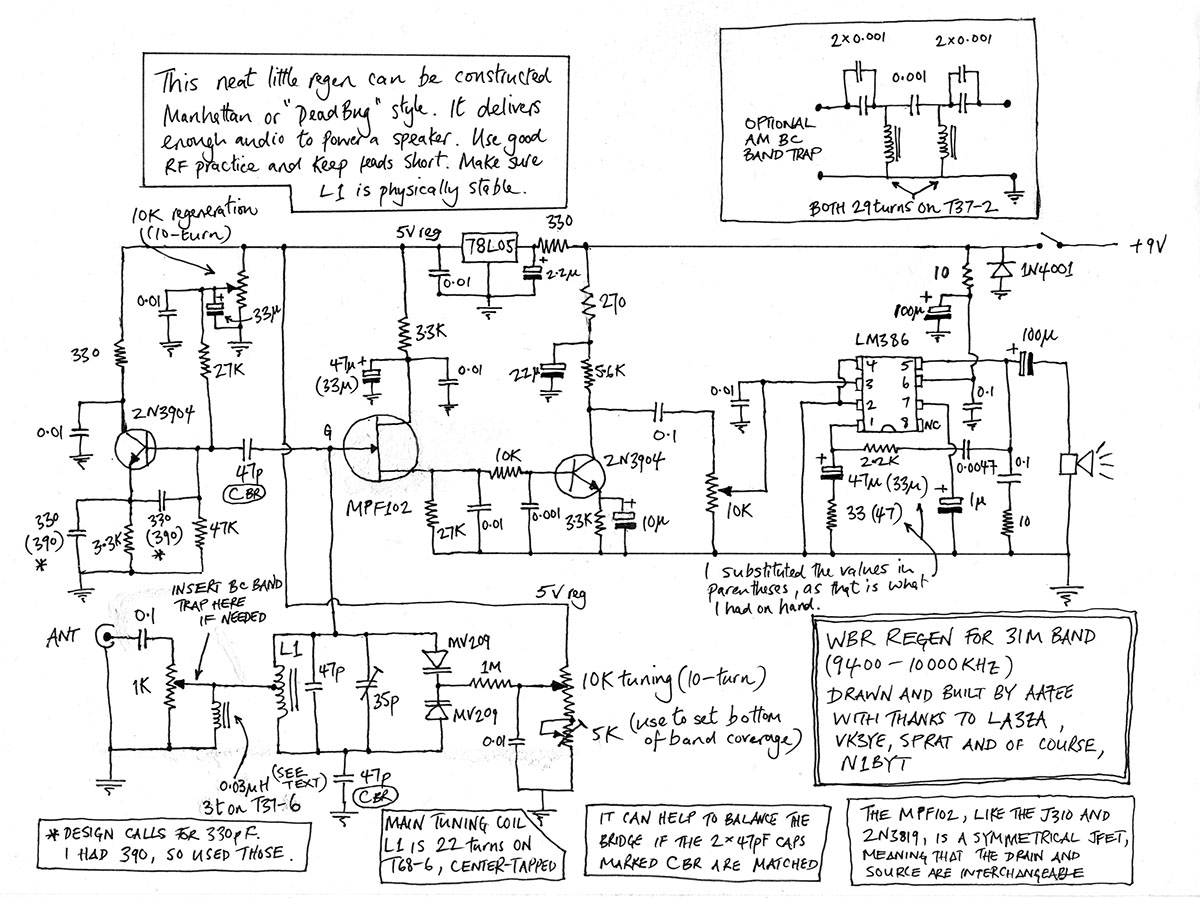
I know there are some experimenters who are sitting on the sidelines waiting to build a WBR, but who are a little confused by the various mods published, and want to see more information on a successful build before going ahead with their own. By sharing detailed information on mine, I’m hoping a few more people will be encouraged to build their own version and share their experiences – the internet is a great way to do this. Many thanks to Dan N1BYT for graciously giving me the go ahead to show you a full schematic for this version that I built. The only changes I made to the core part of the circuit (the regen stage and the infinite impedance detector) were to employ a 10-turn pot for the regeneration (with a 33uF cap across it to stop the “whizzing” sound), the addition of the trap, and the substitution of Z1 for a small toroidal inductor, a mod that was first publicized by LA3ZA. The actual value of this inductor may require experimentation on the part of the individual builder but, and this does bear repeating, it is wise to err on the side of keeping it small in order to avoid detector overload. My 40M WBR uses just a piece of stiff wire for Z1, and I have never heard any kind of breakthrough from all the signals my outside antenna delivers to that defenseless little receiver!
The description of circuit operation is contained in the original article which is readily available to ARRL members. Having read horror stories of unstable and unpredictable regen behavior by some builders (not of the WBR, I hasten to add), I was pleasantly surprised to find that the WBR has smooth regeneration control with no hysteresis, and is overall a tame set to operate. I have read that for solid state circuits, the designs that incorporate a separate Q-multiplier and detector (as does the WBR) tend to work better. Whether this is fact or hearsay, I am not sure. I have found it quite difficult to separate technical fact from folklore in the area of regens. This could be partially due to the fact that many builders, like myself, don’t have an in-depth knowledge of the workings of these circuits. Add that to the fact that regens are particularly dependent on good RF practices and solid physical construction, and I suspect that some designs are declared to be wanting simply because the experimenter didn’t build it properly. Likewise, due to lack of knowledge on the part of many builders, marginal regen designs are published and propagated by people who don’t have the ability to discern whether a circuit is “any good” or not. The world of regens seems to be a mystical and magical one inhabited by equal parts myth and fact.
I used 10-turn wirewound pots for both the regeneration and tuning controls (Bournes 3590S-2-103L). These pots aren’t cheap and if you need to save money, you can use a preset to set the approximate regeneration voltage range, and a regular 1-turn pot for the regen control, as N1BYT describes in the original article. If you use a wirewound pot here, add a 33uF capacitor between the slider and ground, as shown in the schematic. This will eliminate the “whizzing” sound as you rotate the pot. I have an affinity for 10-turn pots, so I used them for both controls. I like the fact that I don’t have to bother setting the approximate regeneration range with a preset, as I have the full range of control voltages available to me immediately with the 10-turn control. When using the injection of carrier to receive weak AM stations, the regen control can be used as a very fine tuning control in order to set the receiver to zero beat when in exalted carrier reception mode. Adjusting the regen control does have the effect of slightly shifting the frequency of the receiver, which can come in quite useful when wanting to make critical adjustments to the tuning of the receiver. Incidentally, this is a good reason to pay close attention to the physical construction of your WBR. You won’t be able to set the receiver for exalted carrier reception if it’s not stable enough.
The one disadvantage of using a 10-turn pot for the tuning is that you can’t see at a glance roughly where you are in the band. An arrangement of two 1-turn pots, one for bandsetting, and one for bandspread, will be cheaper, and will allow the operate to easily judge where he is in the band simply by looking at the setting of the main bandsetting pot. Other arrangements might be possible. One thought that comes to mind is the use of an old-fashioned vernier reduction drive with a logging scale connected to a 1-turn pot. This would allow for quite accurate calibration of the dial and of course, the ability to see where you are in the band with one glance. The expense and trouble may not be justified, but if you already have one on hand, it would be an intriguing option. Expanding on this – how about a version of the WBR with plug-in coils for wider coverage? The padder and trimmer capacitors could be included in the coil form so that each frequency range could be adjusted individually. Well – that may be too fanciful an idea, but imagination is free! If you’re using a 10-turn pot, how about one of those turns counter dials combined with your own personalized logging chart? This is an idea I may try to implement in my build of this receiver at some point.
When setting the frequency coverage, you can run a short piece of wire from the antenna lead of a general coverage receiver close to the main tuning coil of the WBR and turn the regen control in order to make the set oscillate. Then, listening to the WBR oscillator in your receiver and with the tuning pot in the WBR turned fully clockwise, set the trimcap for the uppermost end of the desired frequency coverage. Twist the WBR tuning pot fully counter-clockwise, and use the 5K trimpot to set the bottom of the tuning range. With the values given, I was able to get my WBR to receive as high as 10.3MHz and lower than 8.6MHz, giving me the ability to pick any 500-600KHz tuning range within those limits. It would be a fairly simple matter to set the WBR to receive on any desired band of frequencies by changing the number of turns on the coil and/or the value of the 47pF padding capacitor (the capacitor in parallel with the trimcap).
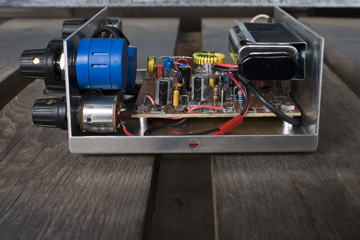
Here’s the basic board. At this point, the only inductance between the center-tap of the main tuning coil (the big one on the yellow T68-6 toroid) and ground is a short piece of stiff wire. Also, the AM BC band trap hasn’t been built yet (I didn’t know that I would need it). The cables for the various connectors have been bundled together in order to look neat for the picture –

On connecting this board up, the receiver seemed a little deaf, To be fair, although the original article doesn’t mention it, corrections to the article published in a future edition of QST did mention that Z1, the impedance between the center-tap of the coil and ground, should have been drawn as a metal strip 1/8″ wide, 1’2″ long, and grounded to the board with a standard piece of wire. I was using just a piece of wire, as you can see in the photo. This probably wasn’t providing enough inductance. I clipped part of the wire connecting the center-tap to the ground plane, and inserted an inductor consisting of 9 turns of wire on a T37-6 toroid. This is an inductance of about 0.3uH. Wow – what an improvement in sensitivity! Unfortunately, a local broadcaster whose transmitter on 1640KHz is just a few miles down the road from me, was breaking through. This was presumably caused by detector overload as a result of increasing the impedance at Z1. I added a simple AM broadcast band trap which I initially thought had solved the problem, but later discovered that the breakthrough was still there, albeit at a much lower level. I rewound the T37-6 toroid with 4 turns, for an inductance of about 0.05uH. Bingo! Breakthrough gone! In retrospect, a better way to proceed would have been to attempt to find an optimum value for the inductor that would have given good sensitivity while still avoiding overload of the detector, before adding the trap. Here’s the board after the trap was added, and the center-tap of the coil modified. The stiff wire to ground was cut and a 10M stand-off resistor inserted in it’s place to help with rigidity, before adding the inductor wound on the T37-6 toroid. This is the first version of the inductor, with 9 turns. The later version had just 4 turns –

Time to box it up. I’ve had a couple of small aluminum cases from LMB Heeger that I bought because I thought they’d make great cases for small projects. It’s their model #143 in plain aluminum finish, though it is also available in grey and black. One thing I particularly like about it is the small lugs on the top cover – 2 at the front and 2 at the back – that prevent the front and back panels from flexing inwards. This feature helps to make it a very stout little case. This enclosure was the obvious choice to make a nice compact receiver out of this version of the WBR –


After a few hours of listening to it (what fun!) the AF amp began to make occasional motorboating-type noises. It appeared that audio peaks were changing the regeneration point and pushing the set into slight oscillation. The battery was still at about 8.5V, so this should not have been happening. While researching possible causes, it occurred to me that in reality, this receiver was going to spend nearly all of it’s time in my shack, meaning that I could run it off the shack gel cell power supply. Instead of solving the issue I took the easy way out, removing the battery holder and fitting a jack for a DC power supply, along with a series diode for polarity protection. The receiver can easily handle the ~0.6V voltage drop from a 12V supply, and if you use the reverse diode to ground method with a bigger 12V supply, it will blow the diode like a fuse if you inadvertently connect the power to the set the wrong way round. With a small 9V battery, it’s internal resistance should prevent it from passing enough current to blow the reverse diode. Also, you cannot afford to drop 0.6V from a 9V supply, hence the reason for using the method pictured in the schematic. The holes that were previously used to mount the battery clips became tie points for the antenna cable –

My downstairs neighbor’s cat was standing over the WBR in this next shot. You can see his whiskers in the top right-hand side of the frame. I think he’s interested in regens. In these next 2 shots, you can also see the lugs on the top cover that help to make this such a stout little case. It’s a neat little receiver –

From time to time, I am asked what knobs I use for my projects. They are manufactured by Eagle Plastics. I get them from Mouser, though I’m sure they’re available through many other outlets.
The large one I use for tuning is part # 450-2039-GRX (the exact same knob is also available from Radio Shack, and is RS catalog # 274-402
The medium sized ones I normally use for AF gain, RF gain etc are part # 450-2035-GRX
and the small ones I use for AF gain, RF attenuation, and regeneration in this receiver (because space was at a premium) are part # 450-234-GRX
For wiring up the connectors, I use a thin cable consisting of 2 conductors plus a shield. It’s made for lavalier mics, so is skinny and flexible – ideal for wiring up pots and jacks. I used to get mine from a local pro-audio store that recently closed down, so had to find a new supplier. Most places online seem to either want to sell large reels of the stuff or, if they do sell it by the foot, charge too much. I found a place in Connecticut called Redco that sell it by the foot for a reasonable price. On top of that, they will ship via first class USPS mail, which helps to keep the cost down. I haven’t tried any of this new batch yet, but it’s a quality cable made by Mogami (type W2697), and it looks like it will do the trick.
RF connections (like from the antenna connector to the RF attenuation pot) are made with Belden 8215 RG-174/U. It’s skinny and flexible.

Following are a number of videos designed to show different aspects of this regen, My old camera takes awful quality video (sorry about that) and limits the clips to 3 minutes, which is why there are several videos instead of one long one.
This one shows how the set has quite a narrow bandwidth when set to the point just below oscillation. In all these videos, the WBR is directly driving an external speaker. There is no external amplifier connected –
In this video, you can hear how the audio bandwidth broadens out considerably when the set is oscillating –
Tuning around the 31M band. There aren’t many strong signals, as band conditions generally have been poor. It’s not due to any shortcomings in the WBR –
This video shows how stable a homebuilt regen can be. I could have made mine more impervious to knocks by holding the toroid with a nylon screw and washers, but that might have introduced more long-term drift –
Another video just tuning around. It cuts off rather suddenly at the end –
This one shows how effective the technique of exalted carrier reception can be – and you can do it with a regen! –
It seems fairly sensitive, and quite stable, both in terms of it’s response to physical knocks, and the long term drift. I like regens over direct conversion receivers, because of their ability to demodulate AM as well as CW and SSB transmissions. I suppose that with a very stable VFO (a synthesized one perhaps) a DC receiver could receive AM in exalted carrier mode but with a regen you can actually take it out of oscillation and receive AM with no carrier injection. The regenerative detector is a versatile one.
The only criticism I have of this particular build of the receiver is that I seem to have a noisy LM386. The 386 stage is generating a type of low frequency random scratchy noise that wasn’t present the last time I used this circuit configuration (in the Micro 40). I have heard that there is enough variation in these chips such that you can get a particularly noisy one. This chip was part of a batch of cheap ones I bought from eBay. I just ordered some LM386N-4’s from W8DIZ. They seem to be quality parts from National Semiconductor and because they are LM386N-4’s, they have higher power dissipation and a higher max supply voltage (16V) than the others (12V), which can’t be a bad thing. I may, at some point, put one of Diz’s 386’s in place of my eBay cheapy-chip in this set. EDIT June 25th 2014 – I just replaced the eBay cheapy LM386 with an LM386N-4 from W8DIZ and the scratchy rumble is gone! The ones that Diz sells are National Semiconductor devices and of course, they still hiss, because they are 386’s being used in a high-gain configuration. With a good 386 though, the noise is just a smooth hiss that is much easier to deal with than the scratchy rumble of the bad part. Here’s what the sub-par IC sounded like. The hiss is normal for a LM386 used in a high-gain configuration, but that scratchy rumble is most definitely not –
Jason NT7S built a WBR using the schematic in this post. Instead of building it for the 31M band, he built his for the 40 amateur and 41M broadcast bands. If I remember correctly, he set his coverage for 6900 – 7500KHz, which gives him coverage of the pirate BC band at around 6925KHz ±, 40M from 7000-7300, and 41M from 7200 – 7450KHz, though it does make tuning SSB and CW a bit tricky. If you want to make tuning SSB/CW easier, then you can limit the coverage of a 40M RX to just the amateur band. If you’re a phone-only person, you could have your WBR tune 7150-7300 (in the US) for much smoother tuning! Before removing a turn from his antenna-input inductor, Jason was getting breakthrough from a strong local station on 1390KHz – even with the AM BCB trapin place. He did a sweep of the trap on his scope and here was the result. The marker is at 1390KHz – the strong undesired signal –

Note how the attenuation of the trap is only about 5dB at the frequency of the unwanted signal. I may take another look at the values of the components in this trap with a view to increasing the cut-off frequency but my first step will be to also remove a turn from my antenna-input inductor to reduce it to just 3 turns and see if I can also manage without the trap. Thank you for this input Jason! Jason’s WBR sounds great. It is the first time he has successfully built a regen, and I’m tickled pink that I was able to inspire him to build this one. I don’t think he was disappointed either –
Jason sent me this picture of his WBR, all wrapped up in a smart blue enclosure. Aluminum for the bottom half, and PCB material for the top half, if I’m not mistaken. I like the attractive pattern of holes for the speaker cut-out. Is the bottom half from an LMB Heeger Crown Royal enclosure, by any chance? Nice! –

This successful build of another WBR is helping to pull me down the rabbit hole of wanting to build the perfect regen. My goal is to build a really good general coverage regen on a nice-sized chassis with plug-in coils for band changes. I am starting to collect parts with this goal in mind and being relatively inexperienced with regens, have many questions in my mind, such as
– semiconductors or tubes?
– separate detector and regen stage, or an oscillating detector?
– an FET or a bipolar detector?
– high mu, or low to medium mu tubes for the detector?
– throttle capacitor with ball drive, or resistive regeneration control?
– toroids or traditional coils?
– any other considerations?
Although I’m secretly looking for a solid technical reason to make my dream general coverage regen a tube design, a semiconductor one would probably be best, as long as I’m not potentially giving up anything in performance. If any experienced regen builders are reading this and have any ideas, I’d love to hear them.
Oh – and the downstairs neighbor’s cat, whose whiskers you saw poking down from the top of the frame in the shot of the WBR from the back? That’s Stephen. He likes regens (I think). Here he is wondering what magical electromagnetic signals there are out there in the ether. He might also be looking at a bug –

Such an enjoyable little receiver. Thank you for the circuit once again N1BYT.

I’m impressed by how much you have achieved with this receiver, Dave!
73 Sverre, LA3ZA
Sverre – thank you so much for publishing your circuit inspired by the WBR, and your work on adding the inductance at the center-tap of L1. Your work has been the cause of many online discussions about this fun little regen receiver!
73,
Dave
AA7EE
Hi Dave,
It’s beautiful! If it works as well as it (inside) looks, you’ve got a wonderful radio. Okay, running to YouTube so I can hear it.
73
Kent
Thanks Kent – it does indeed work quite well. I only wish that I could cover several different bands on it, but that will be the goal of my next project.
Dave
AA7EE
“I have read that for solid state circuits, the designs that incorporate a separate oscillator and detector (as does the WBR) tend to work better.”
In a regen in which detection and Q-Multiplying have been separated into two distinct stages, each stage can be optimized for it’s task. The Q-Multiplier optimized for a smooth regen control and the detector stage optimized for an efficient detection with enough AF-output. When these two tasks are combined into one single oscillating detector stage, performance will suffer. Squegging often occurs in these oscillating detectors due to large RC-timeconstants involved in the base, emitter/siurce or collector/drain circuitry. Detection can also be inefficient on the lower end of the band coverage, because the BJT or FET must be biased in a more linear region to be on the brink of oscillating.
There is a regen which only uses BJTs and in which detection and Q-Multiplying are separated. A minimimalistc differential pair as a Q-Multiplier and a single BJT as an Audion detector, see http://www.b-kainka.de/bastel3.htm
This is great information DrM – I have bookmarked this article for future reading. Separate detection and Q-multiplying stages is definitely the way I want to continue with future builds.
Dave
AA7EE
Got it – Thanks. Great reply for a great project. You are a good dude, dont care what anyone says… 🙂 73’s Dar…
Great to hear from you Dar. I e-mailed you a couple of months ago but didn’t hear back. Hope you’re doing OK!
Dave
AA7EE
Regarding your comment, “In this video, you can hear how the audio bandwidth broadens out considerably when the set is oscillating”: this phenomenon has been deeply analysed and explained (by user “vladn”) here: http://theradioboard.com/rb/viewtopic.php?f=1&t=4680&start=0 . It is, in fact, possible to completely eliminate this phenomenon; bandwidth can be controlled independently of oscillation amplitude (to choose a desired amount of selectivity), and oscillation amplitude can be controlled independently of bandwidth (to control how easy it is for the regen to lock on to the incoming signal: we want a low oscillation amplitude and easy locking for synchronous AM reception, whereas we want a high oscillation amplitude and no locking behavior when listening to SSB). Eliminating this phenomenon, i.e., separating control of bandwidth and oscillation amplitude, can be done by using an explicit amplitude limiter (i.e. a separate transistor/tube stage as part of the oscillator’s explicit amplitude stabilisation control loop) that exhibits scale-independent gain compression. In other words, regardless of the oscillation amplitude, if the oscillator’s gain compression (amplitude limiting) behavior is scale-independent, then the final result of the repeated selective amplification (that defines the final regenerated Q and bandwidth) will be the same, regardless of the oscillation amplitude. See this video (by vladn) for a demonstration of independent control of oscillation amplitude and bandwidth: http://www.youtube.com/watch?v=UyqD99WGlss .
I saw the video (linked I believe, from the Yahoo regenrx group), but haven’t yet read the post you linked on the The Radio Board – thanks for that. This is a very significant piece of work in the area of regens – I didn’t know there was anyone doing work at this level. I am still busying myself with the well-established regen circuits, but it’s great to now there are people advancing our understanding of these receivers.
Dave
AA7EE
On the topic of regen improvements: it’s even possible to engineer the circuit such that the frequency shift with regeneration is reduced to practically zero! This again was a fascinating revelation (again by vladn) for me. Most people seem to take it for granted that regens will exhibit this frequency shift with regeneration adjustment, but it’s quite interesting to see exactly why this phenomenon occurs and to confirm the understanding by removing the phenomenon in a test circuit. See here for more details: http://theradioboard.com/rb/viewtopic.php?f=1&t=5153 . This might not be the only way to attack the “problem” of frequency shift with regeneration adjustment, but it at least shows one clear way of achieving that goal (by keeping the amplifier always operating in class A and relying on a separate limiter, instead of amplifier distortion, for amplitude limiting). OnTheRadioBoard, in addition to vladn’s tube designs, there is some discussion of a solid-state receiver architecture (using 3 JFETs in the oscillator) that achieves similar goals of low frequency shift with regeneration adjustment and independent control of bandwidth and oscillation amplitude. The design ideas can be seen here: http://theradioboard.com/rb/viewtopic.php?f=4&t=5171&start=0 . That will probably be my next regen project (whenever I get around to it…).
Good stuff qrp.gaijin – and I like that you’re questioning whether varactors can be used without compromising performance. If we truly want to bring regen techniques into the 21st century, perhaps we should be looking at something like MEMS capacitors for tuning 🙂
There is something rather wonderful about a good quality air-spaced variable capacitor though……….
Dave
AA7EE
Dave, thanks for the inspiration to build one of these! It worked like a champ right away and is a marvel in the parts/performance category.
Keep up the great work and 73,
Jason NT7S
Jason – I’m tickled pink that you built the WBR. Thank you also for that spectrum of the response of the BCB trap which, it appears, is not as much of a BCB trap as I thought it was (at least, not for the upper part of the band). I need to look at those values again and re-work it for a higher cut-off frequency. I’m also thinking of doing what you did – removing a turn from the .05uH inductor (which would make it a 0.03uH inductor) and seeing if I can lose the trap.
I’m still dead chuffed that you built this!
Dave
AA7EE
Do you have any design / board layouts/ where to buy parts from etc…
No, I’m afraid not. The intention is merely to describe how I built a particular project, and to give enough information so that a builder with some experience can build their version. I didn’t intend these posts to be “how to” articles.
73,
Dave
AA7EE
I’m building this circuit now. Am almost there, but still have some troubleshooting to do. I’m getting audio (and plenty of it) but no signals. Connecting an antenna does not result in the increase in noise that one would expect. So something is awry but I will find it.
Thanks for posting this information. It’s very informative and greatly appreciated!
Steve
It’s good that your audio chain seems to be working, Steve. Is the regen stage oscillating? You can listen for the signal on a nearby receiver. Without oscillation, obviously, it will not work, but hearing oscillation is a major step closer to making the receiver functional. If it’s oscillating, and you hear a rushing sound in the speaker/phones on increasing the regen control past the critical point, then the next thing to look at would be the coupling of the antenna to the tank circuit. Best of luck, and let me know how it goes.
73 for now,
Dave
AA7EE
PS – I like the picture of the white cat on your QRZ page.
Dave, I had a similar problem as Steve, but could never get the regeneration to oscilate. This waz last year. My trouble-shooting skills aren’t the best so I just took it apart, and rebuit it…three times! Still no luck. I wonder if the varacters are the problem? Tnx fod your article, pics and vids. Well done!
de wa4chq
Neil – it’s hard for me to guess what it might be, without any other information. What varactors were you using? Were they “good” – a quick test with a DMM should show a voltage drop of around 0.7V under reverse bias. If you have another go at building it, I can measure some of the voltages at various points in the circuit to compare with yours. I feel bad for you. I’m not sure if I would have had the tenacity to build mine 3 times. I tend to give up easily!
73 for now,
Dave
AA7EE
Thanks Dave….I used to have a shack that was perfect for ‘brewing. I built many qrp rigs back in them fun days….1995-2005…..Them days are over for now at least. So my shack on the boat isn’t large enough to double as a work bench. It’s all apart now and I understand that it’s hard to diagnose online with little to go with. The first build it “worked” the best. hi That was before putting all off board parts on a nice front panel. I should have kept notes. I know I later ordered the 10-turn pots which I suspected being bad. I substituted parts like the fet, varactors, pots etc. thinking that I could at least get the regen to start to squeal. Anyway, I may tackle it again. During my building daze I had a pretty good track record (called luck)hi….anyway I’ll get it to squeal one day…. Thanks for the wonderful blog about your brewing adventures….best 72. Neil wa4chq
Neil, for what it’s worth, I made two attempts and in neither case did I achieve oscillation. I’m very eager to figure out what’s wrong, but I have moved on to other things in the hope that getting a little “distance” from this project will allow me to see what’s wrong.
I decided to revisit this project this afternoon after it sat on a shelf since February.
I was hasty in drawing conclusions before. It turns out there is indeed oscillation….just not where I expected it to be! I’m hearing it on at least part of the 40m band and above. Odd since I used the same toroid with the same number of turns as you see on the above schematic.
I also find that I cannot get the rig to go into oscillation through the entirety of its tuning range. In fact, oscillation is impossible on about 2/3 of its turning range! So, something is definitely off here. I will continue to investigate it, but I feel that progress may be possible now. Oscillation is better than no oscillation!
Some progress. The receiver now works quite well with headphones. The volume control is quite critical, going from almost no volume to a listenable level very quickly, but it is working. However, there is a problem when attempting to use a speaker. For the most part, the rig just squeals when connected to a speaker, except for one small range of volume adjustment where there’s no squeal but the volume is extremely loud. If I try to lower the volume, the squeal returns.
I am not using an amplified speaker or anything like that. I will continue to work on it.
It was an impedance issue. I didn’t realize that my headphones had a significantly higher impedance than my speaker. A 27 ohm resistor connected to one of my speaker terminals solved the problem.
Steve – glad you solved the problem, and my apologies for not replying sooner,
73,
Dave
AA7EE
I’m planning on building one or two of these for different bands. 40m for sure, and I wouldn’t mind building one for 22m so I could listen for HiFER beacons. Is this a terrible idea?
How would one go about modifying it for that band if it isn’t a terrible idea?
Not a terrible idea Dayne. Quite a novel one, in fact. Personally, as the HiFER band is so narrow, I think I’d prefer a highly stable receiver with a digital readout.
As far as how you’d go about modifying it, I’m afraid I have very little time for radio these days, so don’t have the time to do the rough calculations for the HiFER band.
73 for now,
Dave
AA7EE
Dave – I built this receiver about a year ago and I was really impressed! I redesigned the circuit to pull in the 20 meter band, and there are times when I have to turn the volume way down because reception on some evenings practically blow out the front end! I’m using a random length wire for an antenna inside my house! My only challenge thus far has been replacement of the 10k 10-turn pots. They got a little “scratchy!” To calibrate my main tuning range, I listen to my radio and one of the WebSDR HF online receivers at the same time! In my opinion….a great little receiver!
73,
Brett Shepherd
WB0KRQ
Brett –
It’s really good to hear that others have had success with this little receiver too Brett. I find it amazing to be able to hear the same stations on my simple homebrew regen that I can on my more complex and expensive receivers. Great stuff – thanks for letting me know!
73 for now
Dave
AA7EE