

Note – all links in this post open in a new browser window. Many thanks to Zach N0ZGO, for providing updated links. I have edited this article to reflect them. Thank you Zach!
I’ve been wanting to build an SST for a few years now. It’s a plucky little rig, with a lot of character. Designed by Wayne N6KR in the late 90’s, appearing as a full article in QRPp, and a kit sold by Wilderness Radio, it ignited the imaginations of a whole generation of builders for it’s combination of simplicity, performance, and willingness to accept modifications cheerfully. The review from Adventure Radio Society was quite positive. It is a VXO-based QRP CW transceiver, with a simple superhet receiver (SST = Simple Superhet Transceiver), and a TX that puts out up to 3W, depending on your choice of transistor in the final (it can be dialed down for battery-powered outings). It has very fast, clean QSK – so fast, in fact, that it feels as if I can hear the band all the time I’m sending (W6JL would approve). You actually listen to your own signal as you’re sending – there is no separately generated sidetone. The sidetone level does vary with the volume control, as opposed to being a fixed volume, but I only find this to be an issue when I have the AF gain all the way up, in which case I either quickly adjust the volume knob, or partially pull the earbuds away from my ears while sending. By the way, the sidetone on this little rig sounds really nice. It’s a feature which helps to make operating the SST an enjoyable experience.
QRP’ers loved their SST’s. There was a lively discussion about the minimalist rig on QRP-L, with builders reporting back on the frequency coverage and performance of their builds, with details of mods they were trying. The kit came with a light gauge unfinished aluminum enclosure. The raw-finish aluminum was a blank slate which invited many different creative solutions to the age-old question of how to show off your project. Some folk endowed theirs with professional-looking paint jobs, while others used dymo labels, or simply scrawled right onto the panel with a Sharpie® for that authentic home-brew look. All approaches worked admirably well. I saw one SST that had been painted with a US flag, and looked great. Some of them were taken out on the trail many times, and showed many knocks and scratches on the case which, of course, just made ’em look better still.

Recently, I decided it was time to build my own SST, only to find that I had missed the boat on a kit, as Wilderness Radio had discontinued it at some point in the recent past. I called QRP Bob on the phone, hoping that there would perhaps still be a board and/or enclosure available, but I was out of luck. In fact, it meant that I was in luck, as I would have to scratch-build one, and that’s a good thing.
There is plenty of documentation for this rig online. The initial write-up was in the Spring 1997 edition of QRPp, available from Chuck K7QO here. Note that the preceding link is a PDF of all 4 volumes from that year. The entire QRPp archive is also on Chuck’s site and accessible from his main page. Other essential documentation is the mods and information collected from QRP-L messages from 1997-2004, from Ken Larsen AL7FS, here.
Mine differed just slightly from the original. Here’s my hand-drawn version of the schematic, reproduced here with kind permission of N6KR. Don’t rely just on the following schematic, as my drawing is a bit goofy. Best to refer to the original circuit diagram in the manual (available here), and use mine to see how it differs –

Component designations (e.g. C27, R11 etc) are the same as in the schematic in the Wilderness Radio manual. There are 3 parts in the above schematic that do not have such designations – they were added by me (the series capacitor and resistor from pin 5 of U3 to ground, and the 1N5817 diode in series with the 10-16V DC supply line).
Differences between the stock SST and mine are –
1) Inclusion of a series diode in the supply line for polarity protection. I did consider using a P-channel MOSFET so as to avoid the voltage drop, but decided to go with a Schottky barrier diode. Some diodes of this type have a big enough reverse leakage current such that they are not effective in this role, but not so the 1N5817. It’s forward voltage drop is about 0.34V in transmit. I still don’t like losing that much, but it’s an improvement on the higher drop of a regular silicon diode.
2) The use of trimcaps in the RX and TX oscillators in order to place the received signal in the center of the passband, and to put the TX signal on the same frequency as the RX signal. I’m still about 20Hz off due, I think, to touchy trimcaps, but it’s close enough – until I get the urge to tweak and adjust again 🙂
3) The use of 68pF capacitors for C19 and C20 instead of the 100pF values specified. With 100pF feedback caps, my VXO wouldn’t oscillate, so I swapped them for 68pF ones, and it sprang into life (thanks to LA3PNA for the help on that). It may well also have oscillated with 82pF caps, and that is an option if you want your frequency coverage to be a little lower.
4) An MRF237 was used for the final instead of a 2N3553. This substitution was suggested in the manual for higher output power, as the MRF237 has higher gain. If you want a cheaper and more modern alternative to the 2N3553, I’m thinking that a BD139 should work as a direct replacement. Joel KB6QVI just told me that W8DIZ has the 2SC5706 at 10 for $4, and I’m wondering how it would work in this application.
5) A Zobel network was added to the output of the LM386. Mine was unstable at high volume settings. A series capacitor and resistor from pin 5 to ground is very commonly used in these circuits, and the inclusion of these 2 parts tamed my instability immediately.
6) Alternate values of the capacitors in the crystal filter were used to widen out the response. The original values were reported to be giving a particularly narrow bandwidth of around 200 – 300Hz at the -6dB points. I wanted something a bit wider. There were several suggestions in the QRP-L archived discussions. K7SZ tried widening his SST20 out with the help of these suggestions, but it still wasn’t wide enough for him. He suggested the use of 47pF for C6 and C9, and 120pF for C7 and C8, which is what I used. Thanks Rich. A few builders went further, and implemented the ABX (adjustable bandwidth crystal filter) mod that was used in the Wilderness Radio version of the NorCal Sierra. EDIT – K7SZ notes in his ARRL book “Low Power Communication” that his mod brought the center frequency of the filter down too low for him on his SST30, so he ended up going back to the stock values. I have found that using the values of C7/C8 = 120pF and C6/C9 = 47pF that Rich suggested on QRP-L for his SST20, I set the sidetone at 400Hz ( a new thing of mine – I’m experimenting with lower than normal sidetone pitch), and the center of the filter passband was still about 20Hz lower, which I guess is pretty close. If you like higher sidetones though, you may be better off with one of the 2 sets of stock values in the SST manual. SECOND EDIT – I plan to tighten the response of the filter, by using the alternate values quoted in the manual. After using the SST for a while, I think my version is a little wide.
Although the SST didn’t come with a keyer, many users added their own, the Wilderness KC1 keyer and frequency readout being popular. At the time of writing, this is still available – the only kit that Wilderness still supplies. I decided that I wanted to build a keyer onto the same board as an integral part of my SST. I didn’t need much in the way of special features, my only 2 requirements of a keyer for this rig being that it will operate in iambic mode B, and that it has a speed pot – a feature I think of as essential. Changing speed on the fly during a QSO is tricky if the option is accessible only via menus, but a piece of cake if all you have to do is reach out and twist a knob. Perhaps I didn’t look hard enough, but the only freeware I found didn’t support a speed pot. I remembered how well the N0XAS Super PicoKeyer that Dar W9HZC had given me had worked, and a light went on in my head. Dale sells spare chips for his PicoKeyer Plus at $6 each. I purchased 4, used one in this rig, and saved the others for future projects. The manual on Dale’s site will give you the info on all the features of this keyer, and how to access them. The surrounding circuitry is simple (the genius is in the coding), so it was easy to incorporate into the SST –

The keyer uses a piezo transducer to announce the responses to command inputs made via the CMD pushbutton and the paddle. It would be possible to feed this audio into the AF amp of the SST so that it can be heard in the earphones, but I elected to fit a small piezo transducer on the edge of the board. I had intended to punch a small hole in the side of the case to make it easy to hear, but this appeared not to be necessary. Note that in the schematic, I have called it a piezo “buzzer”. It is actually a transducer, but allow me to explain. There are piezo buzzers available to which you apply a voltage, and the unit rewards you with a loud piercing tone, generated by an internal oscillator. Some of the units available are called piezo buzzers, but they don’t contain the audio oscillator – just a transducer, which is often sharply resonant at a specific audio frequency, to enhance the volume of the emitted tone. I bought a 5-pack of so-called “piezo buzzers” on eBay. They looked too small to contain an internal oscillator and I was correct – they consisted of just the transducer, which was exactly what was needed.
This build looked great when it started (as they all do 🙂 ). A nice, clean board, with nothing but potential. As projects progress, I tend to become more anxious that in a single unconsidered moment during a late night soldering session, the iron will slip, the odor of burning plastic will waft into my nostrils, and all the hard work will be undone in a careless fraction of a second. In truth, there aren’t that many errors that can’t be corrected, but this early shot of the board was the best it ever looked! As with all my projects, all the Manhattan pads were MePADS (for IC’s) and MeSQUARES (for everything else) from Rex at QRPMe –

If you compare the above photo to later pictures, you’ll notice that I ended up changing the layout of the front panel controls.
In the next picture, the AF amp and the VXO have been constructed, as well as the 8V regulated supply line. Temporary DC and headphone jacks were also connected, so the circuit can be plugged in to see if it works. The shielded cable that connects to the tuning pot was installed, but left longer than needed to allow for the final install in the enclosure. Not too much of the circuit had been built at this point, but it was already possible to test the voltages at the input and output of the regulator, as well as ensuring that the LM386 made a nice, loud noise when the input terminals were touched with a screwdriver (a highly controlled and accurate test 🙂 ) The VXO was tuned in on a nearby receiver and tested for frequency coverage. With the 20M version, the VXO is in the 18MHz range, and by subtracting the IF of 3.932MHz from the highest and lowest frequencies it oscillates at, you can estimate the final coverage of the SST, and make adjustments at this stage if you wish. The discussions on QRP-L (which are linked earlier) contain a lot of info on tailoring the coverage, so I won’t repeat it all here, but your options involve using different varactors, connecting a second crystal in parallel with the VXO crystal, using different values of rubbering inductor, and adjusting the value of R5. I won’t explain how these all affect the frequency coverage and stability, as this is discussed at length in the QRP-L archive and also, to a certain extent, in the manual. There is plenty of homework reading to be done if you are thinking of building this rig!

Here’s another view, with the VXO in the foreground –

Suddenly, the product detector and BFO burst onto the scene. In the next shot, the 3.932MHz BFO crystal is the one closest to the camera, with the trimcap for centering the passband just behind it. I used 60pF trimmers, as that is what I had the greatest quantity of. Something a little smaller might have made the adjustment less touchy though. I’ll leave you to experiment, if you want to. Things are getting pretty exciting at this point, because when you a touch a wire or metal screwdriver screwdriver to pin 1 of the product detector IC U2, you hear honest-to-goodness atmospheric noise – a distinctly different sound from what you hear when touching the input of the AF amp IC. It’s instructive, not to mention really cool, to hear this progression in the sounds you hear, as you touch the inputs of stages closer and closer to the antenna, as the build progresses. If you have a signal generator, you can inject that into the circuit, and look at the output on a ‘scope. Don’t despair if you don’t have a full stable of test gear though – it’s important not to underestimate the power of touching and listening. Once you’ve done it a few times, you get used to knowing what sorts of things you should be hearing. See the curved red power wire that supplies 8V regulated to the BFO/product detector? You’ll notice in later photos that it was replaced with a different-shaped wire. It’s rarely possible to get everything right the first time you construct something, so one-off builds like this tend to morph somewhat as they progress. It’s OK to change things as you go along –


The next stage to construct was the crystal filter. Do you notice how, on the board for the kit version of the SST, the crystals for the filter were lined up with the short edges parallel to each other, so that the filter takes up a significant length of one side of the board? You usually see filters with the long edges of the crystals lined up parallel to each other. I don’t know why Wayne did it this way, but it did occur to me that with this physical configuration, the input and output of the filter are further apart than they would be with the more conventional placement pattern. Perhaps this was an attempt to decrease the possibility of filter blow-by? It seemed like a good idea, so I replicated it in my Manhattan copy. The crystals in the filter are not yet grounded in this next shot –

As far as matching the 3 crystals for the filter, I placed them into an oscillator circuit, and measured the frequency of oscillation. My cheap Chinese stand-alone frequency counter only had a resolution of 100Hz, but then I remembered that my K2 had a built-in counter with a 10Hz resolution, so I used that. I needed 5 x 3.932MHz crystals total – 3 for the filter, and the other 2 for the oscillators in the TX mixer and the BFO/product detector, so I picked the 5 that were closest in frequency. Out of that group of 5, I took the 3 closest and used them for the filter, while the other 2 were used for the local oscillators (but not the VXO, which required an 18MHz crystal).
To verify that the receiver is working, you’ll need to also build the antenna LPF, consisting of L1, L2, and associated parts. Without it, you won’t be able to peak the antenna input trimcap C1. Notice that if you touch the input of the crystal filter, the noise from the phones sounds much more restricted than when you touch the output of the filter. In fact, you can work your way back through the filter, with the rushing atmospheric noise becoming more and more restricted-sounding as you touch each stage of the filter with your metal screwdriver. These quick checks help to confirm that your project is pretty much on track. Adding the receive mixer means that the receiver is complete. After peaking C1 for maximum band noise, you should be able to receive off-air signals. Congratulations! If you substituted a trimcap for C10, you can also adjust it to place the received signal in the center of the passband, an adjustment that will depend on what pitch of sidetone you like to listen to.
My receiver didn’t work particularly well at first – I was getting very low audio out of it. One or two posts in the QRP-L archive made the same observation. I was beginning to talk myself into believing that the design was deficient in the audio department, and resolving to substitute a different audio chain, when I discovered that the coax which delivered the output of the VXO to the input of the RX mixer wasn’t properly soldered at the output of the VXO, resulting in low drive to the RX mixer. Re-soldering the joint solved the problem, and I can happily report that the audio output is more than adequate to drive a quality set of earbuds or a pair of reasonably sensitive headphones. If you attempt to drive a speaker, you will find that the level is only adequate for monitoring whether a frequency has activity or not, in a quiet room. That’s fine, as this was designed as a trail-friendly rig, with low current consumption in mind, and it certainly achieves that. VK3HN mentioned to me the idea of adding a lower noise AF chain designed to drive a speaker, and retaining the original AF output stage, feeding the inputs of both in parallel. The advantage of this would be that you’d retain the AGC action provided by the LED.
See the VXO in this next shot, with it’s 18MHz crystal? It has a total of just 10 parts, including the tuning potentiometer. I know that it represents old, well-established technology, but I feel that it still has it’s place in ham home-brew. Only 10 parts, and yet it has great stability and signal purity too. As long as you can deal with the fairly limited frequency range, a VXO is still a great choice as the frequency control in a simple rig –

This is always the point, when building a transceiver, where I slow down and spend some time playing with the receiver. I was dead chuffed, as we Brits say, that I had successfully built a little superhet receiver with a narrow crystal filter, that was sensitive, and sounded good.
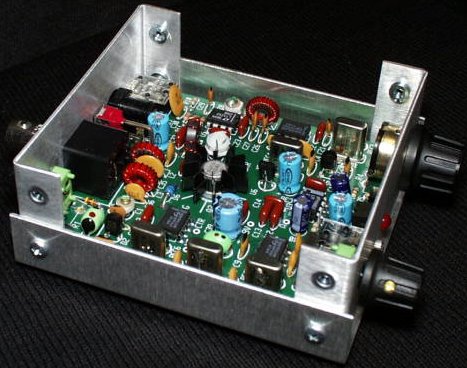
But at some point, the momentum needs to be capitalized on before it is all gone, and so the build continued, with the addition of the transmit mixer. I also added the keying line (the green wires around the edge of the board) so that I could key the TX to see if it worked. If it did, then all that would be required would be to amplify the output of the TX mixer with the driver/buffer, and the PA. We were really getting close at this point! You’ll notice that there is a “channel” of space separating the crystal filter from the rest of the circuit. I did this for two reasons – firstly, as I thought it couldn’t hurt to physically separate the filter a little, to help prevent filter blow-by. Secondly, if there was excessive blow-by, it would give me enough space to erect a screen made from PCB material. C39, the 470uF AGC capacitor, is not present in this shot, nor in the later overhead notated view. I was planning on mounting it off the board, on the inside front panel, but eventually decided to mount it on the board. It ended up occupying the space between the AF amp and the edge of the board –

If you look carefully at these pictures, you may notice one or two components changing position slightly. As the build progresses, I will occasionally move a part or two in order to refine and improve the layout. I’m not going to point out which parts this applies to, as I don’t show these photos with the intention that you follow the layout closely. I started out by following the layout of the stages on the board from the SST manual but as the build progressed, realized I’d be able to move the position of the driver/buffer, thereby freeing up space for the on-board keyer, in one of the back corners of the board. Here’s another view of the board in the same state as in the above photo, with the receiver fully built, as well as the TX mixer. If you have a scope, you can measure the output of the VXO, which should be between 200 and 500mV RMS (that’s 0.565 – 1.414V peak – peak). You can also adjust C28 to peak the signal that will drive the buffer –

This was really the point at which I felt that I was home free. The TX/RX switching was working well, and the rig was putting out a small signal on the operating frequency in the 20M band. All that was left was to amplify it – and even if that didn’t work, I still had a cool little receiver and let’s face it – receivers are cooler than transmitters 🙂
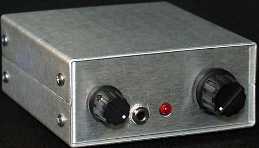
The next shot shows the rig fully built, with the exception of the keyer, with the board temporarily mounted in an enclosure. I ended up changing the layout of the front panel controls, which necessitated the use of another enclosure. In both cases, I used the LMB Heeger 143 enclosure in plain aluminum finish (they also have it in black and grey). I used an MRF237 instead of the 2N3553 in the PA, in order to provide a bit more output, and you can see that transistor, wearing it’s heatsink. To the right of the PA transistor is the orange top of R12, the drive control, and to the right of that is the LT1252 driver/buffer stage. The RF input to the LT1252 is carried by a single wire underneath the board. There are only 2 wires under the board – the one just mentioned, and a length of RG174 coax connecting the output of the VXO to the input of the RX mixer –

A view of the completed board, with the N0XAS keyer in the rear left-hand corner (which is actually the rear right-hand corner, if you are looking at the board from the front panel end). I mounted the keyer chip in a machined socket. I run as many of the control cables as possible underneath, and drill holes in the board for them to enter. I think it looks neater that way –


This next view shows the layout. I got carried away and labeled a few too many parts. The side of the board that faces the front panel is the left edge. As with the previous overhead anotated view, C39, the AGC capacitor, is not shown here, though it did end up being mounted on the board. Remember those SMD SA602’s I was giving away for the price of postage a while back (courtesy of KV7L)? I hadn’t used any myself, until now. 3 of them are in this little rig –

Time to get this thing in a case. The LMB Heeger 143 is an ongoing favorite of mine. It measures 4″ x 4″ x 2″ high, and has 2 small lugs at the front and back of the cover that engage with the front and back panels to prevent them from being pushed in. This feature adds rigidity and stoutness. One of the things I don’t like about most clamshell cases is that the front and back panels can be flexed; not so with this model. It comes in grey and a sort of black wrinkle finish, if you don’t want the raw aluminum. All the pots are Alpha brand. The 3 small ones were $1.29 each from Tayda. The larger tuning pot is also an Alpha part, but is very slightly smoother in action, and I wanted to optimize the experience of tuning this rig. It is Alpha part # RV16AF-10-20R1-B10K-LA (I got it from Mouser). There is a small dummy load plugged into the back in this next shot, because I was having fun using the rig as a code practice oscillator 🙂

The piezo transducer for the keyer was fixed to the edge of the board with a small spot of hot glue (on the high temperature setting of the hot glue gun, as it flows better) –

The keyer CMD pushbutton was a 22 cent cheapie from Tayda. These types are available with plastic and metal shafts. The ones with the metal shafts have a slightly smoother, more positive action. Get those ones. 4 vinyl bumpers from the local hardware store keep the SST from slip-sliding on my desk –

This enclosure is higher than the kit version, at 2″ high. I wasn’t initially planning on such a high case but the advantages are that it supports a larger tuning knob and, as you can see from the next shot, there is room for an internal battery pack, speaker, ATU or other add-on –

Here’s a view of the SST-20 upside-down and from the rear. From left to right – RF gain (rarely used), Antenna, DC power, and paddle –

I have a couple of spare covers for this enclosure, from projects that didn’t go as planned, and am thinking that it would be possible to have different covers with different accessories built in. For instance, one cover could have a speaker and extra AF amplifier, for operation at home. Another cover could contain a battery pack, for portable ops –

The red and yellow knobs look a bit garish, and I’m still getting used to them, but the thinking is that yellow = audio (AF gain and headphones), while red = keyer (speed pot and CMD button). It was also a way of using the cheap knobs I got from Tayda for 49¢ each 🙂

So how does it perform? Well, in 2 words – very well. I don’t operate a lot, but I do spend a lot of time listening. I’ve had 6 QSO’s so far with a horizontal loaded dipole (a Buddipole) at 25 feet above ground at my home QTH. 3 of them were with stations in Colorado, about 900 miles distant, one with KE5AKL who was doing a SOTA activation in NM, also 900 miles from me, and one with a mobile station in Hooks, Texas, who was running 25W. He was 1600 miles away as the crow flies. The other was with a local station. The receiver is as sensitive as you’d need a receiver to be, and there’s a good amount of opposite sideband suppression. I haven’t measured it, but you only hear the opposite side of the signal weakly when tuning through a very strong station. The RF gain only needs to be backed down when in the presence of very strong stations, as the use of an SA602 in the front end can cause it to crumble under such circumstances. I haven’t needed to use it yet, and from what I’ve read, it doesn’t need to be used very often – hence the reason it is on the back panel. My frequency coverage, with an MV209 varacter, is approximately 14055 – 14064KHz, a swing of 9KHz, which is about as much as you’d want when tuning with a 1-turn pot. Many users mounted a switch on the front panel to switch in another varacter (usually an MVAM108, which was also supplied with the kit) to extend the coverage downwards. With the MRF237 in the final, my WM-2 wattmeter indicates an output power of about 2.25W with 11.61V at the input to the rig (11.27V after the polarity protection diode). When supplied with 13.8V from a PSU, the power output was about 2.8W. I didn’t measure the current consumption on transmit, but on receive it is between 26 and 27mA. This is low, but somewhat higher than the 15-16mA quoted in the manual. The keyer consumes <1mA, so that isn’t the reason for the difference.
The AGC LED is a rather unique feature. I’ll let you read up about it in the manual but for the addition of a few extra parts, it will save your ears from the worst ravages of sudden loud signals – and the LED is fun to watch too 🙂 Most red LED’s have a forward voltage drop of about 1.7 – 1.8V. If you want to raise the AGC threshold, look for a red LED with a higher Vf – some of them go as high as 2.2V.
Although all the parts for this little rig are still available, a few of them are a bit harder to find than others. I purchased the LT1252 from Digi-Key – they have them in both through-hole and SMD versions. Chuck K7QO tipped me off to a supplier on eBay who was selling them in 10 packs. I couldn’t resist purchasing a pack. Thanks Chuck 🙂 W8DIZ has the MPN3700 PIN diodes, though see the next paragraph for a worthy substitute. There are several different choices for the PA transistor. 2N3553’s and MRF237’s were available on eBay when I was looking. Try to buy legitimate parts from a reputable supplier (my gut feelings seem to serve me well in this regard). I’m thinking that a BD139 would work in this position too. All the crystals are still available from Digi-Key. The part numbers are the same as in the SST manual, with the exception of X1-X5 for the 30M version. The manual quotes the Digi-Key part # as X007-ND. It is, in fact, CTX007-ND. Perhaps it changed. It has, after all, been 19 years since the kit was introduced!
Even though this design is now quite old, I think it is still very relevant. An experienced home-brewer can build this into a fairly small case, and take it on the trail with a simple tuner and, say, an EFHW, for a compact and effective portable set-up. All of the parts are still available, though it would be great to see a partial redesign, utilizing more modern and widely available parts. I’m thinking of a redesign of the buffer/driver and PA stages. BS170’s are cheap, and 3 of them in parallel, in class E, could provide close to the full QRP gallon. The original SST had room in the case for a 9V lithium battery, and could be dialed down to lower output powers to help battery life. Nowadays, newer battery technologies make more power available in a light and small package, so running 4 or 5W while portable with a small rig like this is practical. Kenjia JH1PJL used an NPN transistor in his driver, instead of the LT1252 IC. He also used a 1N4004 instead of the MPN3700 PIN diode (you can see pictures of his SST scratch-build here). In fact, all the diodes in the 1N4001 – 1N4007 series have the relatively slow recovery time of 30µS, giving them PIN characteristics. Any of them should work fine in place of the MPN3700. If a 1N4000-series diode is good enough for RF switching in the Elecraft K2 (the 1N4007), then it’s good enough for us!
Here’s a brief video of it in action, with a surprise appearance by Jingles the blind kitty. I fed her just before starting the video, and forgot that her routine after eating is to jump up on the desk to relax and digest her meal for a few minutes. I’ll work on producing a slightly better video, though videos are not my strong point. Apologies for the slightly crackly audio. It’s a combination of operator error and a camera that was designed primarily for stills, and not video –
The yellow knob was making me uncomfortable. It has since been replaced with a black one, and I am feeling much calmer now 🙂
10 minutes later, and the red knob has now been changed for a solid and dependable black knob also. I finally feel that I know where I am in the world again 🙂
For the near future, the next tasks are to –
a) add an extra stage to the LPF between the antenna and the rig for greater harmonic suppression and
b) tighten up the crystal filter a bit. I have decided that it’s just a little too wide 🙂
Both the above were done here.
Note – as of early Oct 2016, I received this very informative message from Walt K3ASW –
I have an actual SST20, with several mods.
If you’d like more VXO range, try adding a small value NP0 or C0G from the crystal-RFC junction to ground. Mine has a 3 pF and I get about 14042-14064. However, the VXO voltage to the two mixers (RX, TX) drops by about 1/4 to 1/3 over the lower 2-3 kHz. Also, I have a 1u8 RFC in series with the 5u6 below the crystal.
Currently, it has the K8IQY filter mod, but I’m likely to change that per my crystal measurements and modelling (via W7ZOI’s GPLA).
I added a JFET amplifier (MPF-102) between the crystal filter and product detector ‘602. This reduced the RX noise level quite a bit and I don’t have to run the AF gain as high. This simple circuit is from NA5N’s little handbook he published some years ago. If one does this mod, a dual JFET keying switch needs to be added between the 602
‘product detect and LM386; otherwise, the sidetone is way too loud. (My first version of the JFET switch circuit didn’t work, so I’ll have to try again. It is a tight fit! – on the Wilderness Radio PWB version.)
I’d also noticed the output of the TX mixer needs another filter section. I’m trying to figure out how to shoehorn it in on the existing PWB. (You won’t have that problem with your HB layout.)
I’ve worked quite a bit of DX on mine over the years. When I lived in a condo (before 2000), the antenna was a `98 foot horizontal loop in the attic above the fourth floor and I regularly worked into EU from here in MD.
Hope you like yours; it’s a neat little rig.
73 Walt K3ASW
– and a few days later. Walt sent these extra SST tips –

Yes, the SST is one fine radio. Mine is for 30 meters. BTW I love your work. You are an architectural artist.
Thank you Bob. I was hoping it would work as well as it does. I think N6KR hit the sweet spot of design simplicity and performance with this rig. Love your King Charles Spaniel. They are intelligent and loving creatures!
Dave
AA7EE
Great Job Dave, you really packed it in there. Looks good. Jingles cameo performance was great also.
Thanks Joel. There were a few “smell of melting plastic and cuss word” moments 🙂
Dave
Hi Dave, beautiful job, really glad to see that you are still building. Also glad to see that you have good helpers like Jingles, 73 Mike
Thanks Mike! It’s twice as much fun with the kitties around. Everything turns into a game, as in, “Will I be able to finish this QSO before she jumps up on the desk and sits on the paddle?”
73
Dave
Looking good circuit board,. Tnx for the article. Good pictures. 😍. 73 / Jarmo —>OH1BO
Thank you Jarmo!
73,
Dave
AA7EE
Your creations always look super slick! Don’t know how you do it, but I love reading about it!
Thank you Steve. Like anything, it’s a process. No magic or black art to it!
Dave
AA7EE
Great work – both the SST and the writeup! Jingles is lovely too!! 73, Randy, KS4L
Thanks Randy. Yes – Jingles has me wrapped around her paw. I’d do almost anything for these 3 furry gals who live with me!
73,
Dave
AA7EE
As usual, your rigs are artistic in their construction and layout – yet very functional!
For reverse power protection I have used the self-resetting (PTC) thermal fuses for many years now with a reverse-biased diode on the input supply rail (just “past” the fuse) to “blow” it if the power is connected backwards or the project develop a short circuit such as might happen if the PA transistor were to short out: After the error has been corrected the device rapidly cools and returns to its normal, low resistance – as if nothing had ever happened.
These things are cheap and cause negligible voltage drop and have saved several pieces of my gear over the years, particularly when one is attempting a kludge from an unfamiliar power source and a voltmeter wasn’t handy. I particularly find them handy to be placed in miscellaneous power cables that are connected to a high-current source (a battery) that could possibly be shorted by accident – particularly when those coaxial power connectors with the exposed center connector that seems to be magnetically attracted to ground must be used!
In some cases – where appropriate – I’ve replaced the original “one time” fuse in a piece of ham gear, sometimes by simply soldering the device onto the old, blown glass fuse and putting it back in the holder, selecting the appropriate device for the expected operating current. Of course, these devices aren’t much good for higher voltages (e.g. mains or anything above 30-60 volts, depending on its specs) but that doesn’t matter so much for portable gear.
73
Clint
KA7OEI
I don’t know why I didn’t think of that Clint – thank you for that excellent suggestion.
I recognized your callsign immediately, because when I first got an FT-817, back in the early 2000’s, I spent many, many hours perusing your FT-817 pages. Putting all that information out there is a great service to the QRP community. Thank you! I still miss that little rig from time to time.
73,
Dave
AA7EE
Hi Dave, I tried to send you emails but they keep getting bounced back for some reason, but as always, I am very impressed and inspired with your works. I enjoy your schematics also, and am getting quite a library of them. Keep up the great work and I hope to get in touch with you soon via email.
73 N8RVE John
I just sent you an e-mail John. I have the same e-mail address as before, so that’s a bit odd. Let me know if you receive it. Great to hear from you!
PS – often, after publishing a post, I will find small omissions in the schematics and correct them. If you’re collecting my haphazardly off-kilter schematics, I’d recommend re-downloading them every now and again, just to make sure.
73 for now,
Dave
AA7EE
Dave,
Stumbled upon your YouTube video and saw that the AA7EE Radio Works was back in biz pumping out these flawless beauties once more!
Absolutely breathtaking work snd stunning write-up!
Even appreciate thd touch of Fall with the pine needle snippets!
Vy 71,
de k6whp
The pine needles were already there, so I figured it was just as easy to use them in a photo, than clear them away! Thanks for the kind words, and good to hear from you again Bill.
73 for now,
Dave
AA7EE
Hi Dave,
This is a superb SST, beautifully built, and not easily done considering the density of components.
I am working on my receiver to modify it to become a direct conversion one.
Best regards from France.
Georges F6DFZ
Hi, Do you know how to measure the IF of the SST? If so I would like to know. I installed a Freq-Mite in my SST, but cannot get the readout right. The manual says the IF is about 4 MHz, but that appears to be not enough information to set up the Freq- Mite. THANKS
Am away from home right now. I have not used the Freq-Mite, so don’t know how it accounts for the IF. Will do a bit of reading and get back to you later Robert.
73 for now,
Dave
AA7EE
Robert – what band is your SST for? If it’s for the general portion of 40M, then the IF is indeed 4MHz. If that’s the case, then you don’t need to enter an offset on the Freq-Mite – the Freq-mite is not concerned with the MHz digits. If your SST is for any other band, you’ll need to enter an offset equivalent to the numbers after the decimal point e.g. for the novice 40M SST, where the IF is 3.932, you enter 932 as the offset. If it’s a 30M SST, with a 4.194MHz IF, you enter 194 as the offset.
Remember that whatever band your SST is on, you should program the Freq-Mite for inverted operation – because as the VXO frequency increases, the frequency of operation decreases.
Hope that helps,
Dave
AA7EE
Thanks a lot , Dave. That will do it.
Hi Dave, it is most beautiful Manhattan style I ever seen. Big congrats! I wish you many nice QSOs even to EU! Best 73 – Petr, OK1RP
Thank you Peter!
73,
Dave
AA7EE
Hi Dave. I hate to change the subject but I have a “Sprouty” regen question for ya. I have been going round and round trying to decide on which the next regen to build. The choices so far) are #1Sprouty, #2 VE7BPO #5, or one of my designs that would incorporate a hartley q multiplier, ect, ect. One thing that is important to me in a regen is a very small change in freq with regen adjustment. I have never tried to tame a collpitts osc in this respect. How is the Sprouty in this respect? Todd mentioned it but also he took several precautions aganst it, made mods ect. I have had luck in the past with electron coupled hartley regen oscillators. Have any ideas? Thanks so much for your building, testing, blogs, ect. 73’s, Doug, KM6OR..
Doug –
Yes, the regen control on both of my Sprouties does alter the frequency a little. I can definitely see how this would be viewed as a disadvantage but, when tuning SSB and CW, I have found it useful to use the regen control for fine tuning. It’s more convenient to use the regen control in this way for very fine adjustments, than to adjust the main tuning. With AM of course, it’s a little different, as the exact setting of the regen control is more critical. Ideally, you want the receiver to be just below the point of oscillation. Therefore, a little back and forth adjustment between the regen and tuning controls is necessary. I have not found this to be a problem, but can understand how you’d want a design in which this effect is minimized or eliminated. I don’t have any suggestions, I’m afraid. I have not used anything other than Colpitts oscillators in my regens, with the exception of the one tube regen I built as a teenager. Time to up my game, perhaps!
73.
Dave
AA7EE
Very nice. I’m feeling that I may have to make one. Many thanks for publishing what you have.
Hi Dave, I am very impressed of your work 😀
In summer, I’m going to build a SST for 40 m. Could you please send me a copy of the original manual mentioned? It would be very nice.
73 de IN3EDA, Aaron
I sent it Aaron – please let me know when you’ve received it – or tell me if you haven’t. Good luck with your build!
73,
Dave
AA7EE
Gorgeous construction, Dave. My Norcal SST also uses switched MV varactor diodes but if you want much better dial coverage, simply parallel identical crystals, a process known as “crystal bending.” Both my SST-40 and SST-20 use this technique and I’m able to cover a large portion of the CW band with no detectable drift.
My SSTs both use internal TiCK keyers, having built mine back in the late ’90s before more sophisticated keyer kits became available. Since the TiCK’s Vcc is rated between three and five volts, and the SST’s regulated voltage is +8V, some form of voltage drop was required. While it was possible to use the TiCK’s 78L05 regulator from the +12V supply, I chose to use two red LEDs in series between the SST’s eight volt supply and the TiCK. The LEDs flash in unison with CW and drop voltage within the TiCK’s Vcc ratings. BTW, using a 75L05 from the 8V source would have been marginal, even for a low drop-out regulator. As field battery time wears down, the input to the 78L05 would have fallen below spec.
Paul, W9AC
You could have tried a 3.3V regulator, but perhaps that was a little too close to the bottom end of the acceptable voltage range? There is also the very important deciding factor of which parts are to hand. I like your idea of using LED’s. Flashing things is always a bonus!
I’ll bear in mind the idea of using parallel crystals if I do any similar builds in the future. Thanks for the input Paul!
Dave
AA7EE
A superb project, very neat construction, wish I could do the same!
Thank you Colin. I was pleasantly surprised myself actually, as it was the most dense component layout I have put together with this construction style. It took a while to get to this point. I’ve been building since I was about 8 or 9, and only tried Manhattan a few years ago. My first attempts were messy, though they did work. Practice makes perfect, I suppose, though I have to be very inspired to want to attempt something like this. There are only a certain number of designs which capture my imagination sufficiently to embark on a building spree.
Hi Dave….another nice looking rig! You do nice work. It was you your WBR project that got me looking for MePads. I like how neat you lay your projects out and then package them in sharp looking boxes. I scratch-built the SST back in 2001. Mine is for 40m. It really is a great performer. As you mentioned, the sidetone is quite loud. Thanks for the great articles describing your projects. Best 72, Neil WA4CHQ/qrp
Thanks Neil. I was particularly proud of this project, as it has the highest component density I have achieved so far using this construction technique. Also, I managed it without too many “smell of burning plastic” moments! Good to hear from another SST fan – it’s a classic design.
73 for now,
Dave
AA7EE
Hi Dave
Just reading your article about the SST. Very impressive. Thanks for the ongoing work.
I have just been to UK for about 7 weeks and spent a whole day with Graham Firth G3MFJ. My SSB rig may be published soon in Sprat.
Keep up the good work.
Eric Sears ZL2BMI
Thanks Eric, and I very much look forward to seeing your SSB rig in SPRAT. Keeping my fingers crossed!
73 for now,
Dave
AA7EE
Great build, Dave. I scratch built my SST for 40m in 2001. I put mine in a 2.5 x 4.75 x 1.5 plastic box. It works great other than the LOUD sidetone. I’ve read the mods for the problem but I won’t be able to take mine apart to get to the parts on the circuit board. One of the problems of trying to fit a radio into a very small box. So until I come up with a better solution, all I can do is take the earbuds out before I start to send. 73- Neil WA4CHQ
Neil – here’s some info on reducing the level of sidetone, from Wayne N6KR, taken from the QRP-L archives. Do you have a copy of all the posts on QRP-L concerning the SST? Let me know if not, and I can send you all the supporting info I have on this little rig. My email address is good in QRZ.
73 for now,
Dave
AA7EE
Usually there is a good balance between the incoming signals and the sidetone in the SST. But you’re right–if you have to turn it way up, the sidetone gets loud. The only sure-fire way to mute the sidetone to a lower level is to insert a low pinch-off JFET like a J201 into each leg of the audio connection from the product detector to the audio amp. This is how I do it in the ’40A. Actually you can probably find other JFETs that will work; J310s are mostly low pinch-off, too. MPF102s will work if you hand-select them for low pinch-off. The source leads go to the ‘602 and the drains to the original capacitors that go to the ‘386. Tie the gates together and add a 1 to 10M pull-up resistor from the gates to one of the source leads. Next, connect a diode from the gates to the key input. Test the circuit thus far by keying the rig: you should hear ZERO sidetone at this point, because pulling the gates low cuts off the JFETS, making them look like an extremely high resistance. If you hear a click on keydown, put a resistor (start with 1K) in series with the gate diode. If you hear a click on key-up, add a capacitor from gates to ground; start with about 0.1uF and see if you can go smaller. (It will depend on the pull-up resistor; 10M and .047 work well in most cases.)
Once this much is working, you can add a resistor *across* one of the JFETs (source to drain) to allow some sidetone to sneak through–as much or as little as you want. It will take a large resistor, something like 1 to 15M in my experience. Let me know if this does it! You might also post this message to QRP-L if you have good results.
Thanks & 73,
Wayne
N6KR
Hi Dave. Yes I have the the info from the QRP-L, tnx for the kind offer. The problem I have is the space. Getting to the area and then adding additional parts would require a major undertaking. I was hoping there could be another way. As it is, I have to lower the head phones from my ears before I start to send. I’m not using the rig as much as I did almost 20 years ago so I’ll be fine leaving it as it is. Thanks for the reply, Dave. 73/72 Neil wa4chq
Neil – I just re-read your original post, and realized that you had already told me you had read the mods. My mistake. I know what you mean about leaving well alone. Sometimes, we just want to accept that our homebuilt creations are what they are, and move on with our lives. There are only so many hours in the day!
73,
Dave
AA7EE