
To many, this will be just another Si5351 VFO project, with nothing to distinguish it from the others. In fact, that’s exactly what it is. The “how to” of connecting an Arduino board to an Si5351 board, wiring up a display, and loading the firmware, is straightforward, and well established. To me though, it was a complete mystery. I have been very adept, my whole life, at studiously avoiding anything to do with digital electronics, computing, coding, and the like. When my friends in school were getting excited over Sinclair ZX81’s, BBC Micros, and Commodore 64’s, I was building a one-tube regen, an 80M DSB transceiver, listening to my British military R107 shortwave receiver, and talking to hams on the local repeater on my converted Pye tube VHF base station. I remember wandering into a Tandy store (what us Brits called Radio Shack) in the city of Worcester at some point in the late 70’s, and being greeted by the sight of a Tandy computer – probably a TRS-80 or something similar.
“What does it do?” I asked the salesperson.
“What do you want it to do?” he replied.
This seemed like a strangely non-committal response. Maybe he didn’t know what it did, and was merely throwing the responsibility for finding out back on me? I don’t remember anything about him now, but perhaps he was some gangly teenager who knew little about the stuff he sold, and whose main thought was getting off work so he could go to the pub with his friends? That’s it! He was just trying to appear knowledgeable by giving me a non-answer! This suspicious reaction was quite representative of the way I thought about computers back then. Just as it’s hard, if not impossible, to get the measure of a person if they willfully refuse to reveal anything of themselves to others, so it seemed with computers. These expensive boxes just sat there, doing nothing, except waiting for instructions. Such a disappointing lack of character! How is one supposed to respect a person or an object that sits quietly in a corner, waiting to be told what do? How feckless! Dedicated hardware, however, was different. When you bought a radio receiver, you knew that, on twiddling a few knobs and flicking a few switches, it would receive radio signals. A burglar alarm would alert you to the presence of burglars (well in theory, anyway), and those remote control cars that RS sold by the gazillion were guaranteed to quietly drive your family nuts in the days after Christmas before work, and school, resumed. Computers, on the other hand, promised everything but actually did nothing, until you told them what to do – and even then, there were a myriad of ways in which they could obstinately refuse to comply with your wishes. Not for me!
And so it was that, throughout my adult years, I deprived myself of exposure to things digital. I am not proud of my incurious nature about many things – though, when I am interested in something, I exhaust myself with the sheer intensity of focus. It’s an odd type of blinkered approach to the world that leaves others confused. I can’t say I blame them. The projects I built ran off anything from a few volts, up to 15-20V or even more. 9V batteries worked fine (we called ’em PP3’s), as did the old 12V lead acid battery that would no longer power the family lawn mower, but did a sterling job of powering the radio gear in my bedroom. My circuits weren’t picky about voltage, but these new-fangled digital chips just wanted to see 5V. Really? What kind of a voltage was that? They came with a surfeit of incomprehensible nomenclature too. Words that sounded like something John Lennon would have made up for a song post-1965. Words like NAND. You know, it wasn’t so much that this stuff wasn’t interesting – it was simply that I was really into building little radio receivers, and didn’t see how this digital stuff could help me (I wasn’t very imaginative). I had a small stash of ferrite rods, variable capacitors, resistors, and transistors, and some 9V battery snaps and with that, I had all that I needed. These were the days when loading a program onto a computer meant playing an audio cassette into the “line in” jack of your computer. I just didn’t see how any of that world full of DOS, NAND gates, tiny amounts of RAM, and the like, as well as really weird voltages like 5V, could possibly apply to me. Yes – I was that closed-minded. It’s not hard to see how a few years later, when we all graduated from University, my colleagues went on to successful careers with big technology companies, designing integrated circuits, and building the backbone of the internet, while I moved to Los Angeles and promptly became a DJ 🙂
A few years ago, a friend generously gifted me a Bare Bones Arduino board. I didn’t know what it was. It had header pins sticking out of it but, at that point, I didn’t really know what header pins were, or how to connect to them. I looked at it, and wondered what to do with it. What did it do? How did it do it? What was I supposed to connect to it? I placed it carefully in a box along with some other electronic things that confused my simplistic analog mind, and carried on with my life. Every now and again, I’d take it out of the box, blink at it a few times, and put it back. I knew that Arduino was the new big thing, and something that was going to play a big part in ham radio homebrewing in the coming years but I guess that, with my toroids and air-spaced variable capacitors, I wasn’t ready for it yet. Not that my experience level in this arena was completely non-existent. I had taken part in the beta tests of the Etherkit CC-20 and later, the planned CC1 series of QRP transceivers. These experiences had taught me that I could solder SMT devices, and even replace an SMT ATMega328P with nothing more than a soldering iron, soldering wick, flux, and a sharp blade. It was a small revelation to learn that I could do this stuff. Jason NT7S very patiently walked me through the process of flashing the firmware onto the ATMega328 via the ICSP header mounted on the board. This was a first for me, and quite exciting to gain a new skill, which proved handy when I built the SPT “Sproutie” Beacon, and needed to flash firmware onto the ATtiny13 in that little transmitter.
Then, recently, I took the Bare Bones Arduino board out of the box which had been it’s home for a few years and, this time, something clicked. “Goshdarnit” I thought, “I’m going to make an LED blink. If others can do it, so can I!

I spent a few days and nights with the LED blinking and pulsating at various rates, as I loaded different sketches, and adjusted the parameters. As fun as flashing lights are to a simple lad like me, it wasn’t the reason I wanted to resurrect this little Arduino board from it’s relaxing life in storage. I had an Etherkit Si5351 Breakout Board that needed to have life breathed into it. I wanted to generate RF, by golly!
This next stage was where things started to come into focus, and it began to dawn on me that using one of these little breakout boards to generate a stable RF signal wasn’t all that hard at all – well, from the point of view of the end user, at least. Once I did a bit of reading up on how to control the Si5351, I was just a little gobsmacked. You mean all it needs in terms of data input is 2 connections? SDA (serial data) and SCL (serial clock)? That’s it? I made those 2 connections between the Arduino and Si5351 board, uploaded the Etherkit Si5351 example sketch, and almost fell off my chair when the Si5351 began emitting RF on the frequency I had entered into the sketch just before uploading it. It was a moment of realization – that this little board actually was a programmable oscillator. How incredibly neat! No more custom-cut crystals – for ~$10, you can get a board like this, and program it to the frequency of your desire (within it’s specified limits), and it replaces both the crystal and the oscillator. For a single frequency, once you have programmed it, it doesn’t even need a micro-controller connected to it. Fantastic!
I suppose that was the moment at which my mind, which moves at the speed of molasses, “got” that a VFO with this board is really a micro-controller which, with the help of a rotary encoder, is re-programming the Si5351 “in real time” as the encoder knob is turned. Every single click of the encoder sends a new instruction to the Si5351, to step up or down, in an increment which the firmware has already specified. I was hot to trot, so began looking around for a basic Si5351 sketch. The word “sketch” reminds me of the Etch-A-Sketch which I never came close to mastering as a child. I must admit that I think this association slightly trivializes Arduino programs (which are written in a type of C) in my mind, but that is what they are called, so that is what I will call them.
What I was looking for was a sketch that would allow me to vary the frequency of the Etherkit Breakout Board continuously in the HF region, from at least 3 – 30MHz. I was only concerned with one of the 3 clock outputs. At this point, I simply wanted to use it as an HF signal generator for testing purposes, or to control a general coverage direct conversion receiver. Perhaps at some point, I’ll begin fiddling around with code, and learning how to modify it for my own purposes, but at this point, I wanted a sketch that I could upload to the programmer, and immediately be in business. I also wanted to use one of those tiny little OLED displays, due to the enclosure I was considering. This was the point at which I found Thomas LA3PNA’s sketch entitled, “A simple VFO for the Si5351 for either LCD or OLED.” Perfect!
This was also the point at which I discovered that the ATMega168 in my little Arduino clone board didn’t have enough memory to hold Thomas’ VFO sketch. I considered purchasing a newer Arduino board or clone, but most of the ones I saw had more stuff on them than I needed or wanted, in terms of inputs/outputs and programming ability. All I wanted was the ATMega328P, and a 6-pin ICSP header to program it with. Then I remembered back to my time working on the Etherkit CC-20 beta, and how I had expertly fried the micro-controller. Jason sent me a replacement and, wisely, included a few extras, in case my prowess at destroying delicate chips were to reassert itself. I still had those little SMT ATMega328P’s lying around, as well as a supply of breakout boards to mount them on. Problem solved! Building something from parts on hand is so much more satisfying than purchasing a ready-made solution – at least, for the first time, it is.
I sat down to scribble out a schematic, and it was during this process that the realization hit, as to what an Arduino board is. What makes Arduino, well, Arduino, is not the board, but the software platform that supports it. Apologies for stating what is well known fact to many readers, but this had all been previously unknown to me. The board itself is really just a micro-controller, with the power supply and input/output options either suited to the tasks at hand or, in the case of a larger and more general purpose board, such as the Uno, many different such options, to make it as versatile as possible. Ths was fantastic, because what it meant was that all I needed to control the Si5351, was a micro-controller (ATMega328P), a 16MHz crystal with the two associated capacitors, a 5V power supply, and some 0.1uF capacitors for bypassing. Oh – and a 6-pin header for programming. The schematic for the VFO is simple because, as far as the hardware goes, everything happens inside the micro-controller and the the Si5351 (which are both internally complex). The rest of it happens in the firmware. As far as hardware goes, we’re simply tasked with the 21st century equivalent of assembling a crystal set.
Here’s what I came up with. There are an awful lot of unused pins but, for this purpose, there are a lot of pins we don’t need. Without thinking, I was about to connect the AREF pin to +5V, because that’s what I was seeing in the various schematics I was using as references, until it occurred to me what AREF stands for. It’s an Analog REFerence pin. This application uses only digital inputs and outputs, so figuring that I didn’t need an analog reference, I didn’t connect it –

While planning this little VFO, a number of questions were presenting themselves to me. The main one concerned the issue of both the Si5351 Breakout Board and the OLED display being connected to exactly the same SDA and SCL connections. The I2C protocol does allow for multiple devices on the same line, but my understanding was that if more than one device is employed, then the firmware needs to include the unique address of each device. Would Thomas’ sketch work from the get-go, I wondered? As it happened, it did and, as of writing this, I don’t know if this is because
a) the address of the OLED was included in the library definition for this little display, or
b) with a setup like this that only has 2 devices connected, the instructions for the OLED are ignored by the Si5351, and vice-versa.
I’d like to be able to describe the exact steps I took when setting up the sketch, but I have, lamentably, forgotten them. I do remember installing the UG8lib library in the Arduino IDE, which supports the commonly available OLED displays. I also remember, at some point, uncommenting a line that specifically refers to devices that have an SSD1306 driver chip. If you purchase a cheap monochrome 128 x 64 OLED, this is probably the driver chip your display will have. These little displays are available for <$3 including shipping. Deal!
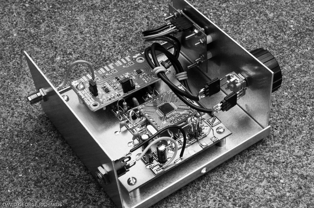
Here’s the ATMega328P mounted on the breakout board –

The controller part of the circuit constructed, with it’s supporting components. No power supply yet, as during initial testing, it will be powered through the ICSP header –


And with the Etherkit Si5351 Breakout Board fitted. The I2C control lines and 5V supply line are connected underneath the Etherkit board –


It took a while to figure out how to mount the OLED to the front panel. The 4 mounting holes are sized for #2 screws. I thought of running 4 #2 screws from the front panel, straight through to the OLED, and spacing the display away from the panel with 4 #2 nuts. The nuts were so close to the glass covering the display though, that they could have cracked it while being tightened. In retrospect, stacked #2 washers might have worked, though long before thinking of that, I came up with this rather more complex solution. It involved a small piece of PCB material, drilled and cut to size. #2 shakeproof washers and 3/16″ x 3/16″ nylon spacers were also employed. Their use should be apparent in subsequent photos –

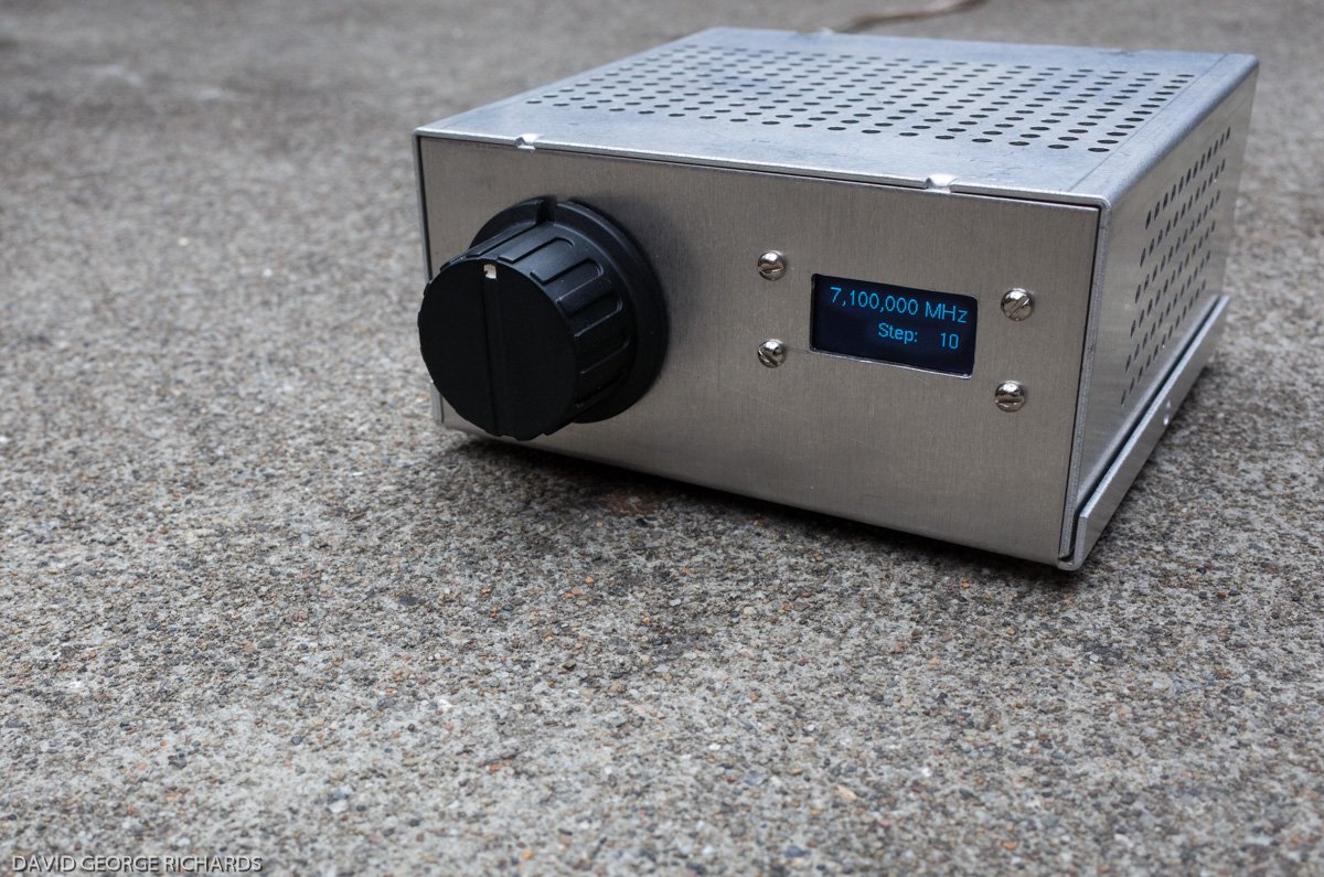
I seriously considered fabricating a PCB enclosure for this little VFO, even getting as far as cutting some of the main pieces. The primary reason for wanting to use a custom enclosure was that the other case I was considering (which I ended up using) was a little too high. As a result, the front panel had, in my opinion, too much empty space. A PCB enclosure, about 4″ x 4″ x 1.5″ high would have looked mighty spiffy. However, I didn’t have the mettle to go through with it. I just couldn’t get quite inspired enough to put all that extra work into making a custom enclosure, and fell back on my favorite ready-made enclosure, the 143 from LMB Heeger. It is 4″ x 4″ x 2″ high, and available in plain aluminum finish, smooth light grey paint, or a sort of wrinkled black finish. They are also available with either an undrilled cover, or a perforated cover. The encoder was connected using header. The main reason for this was that I wasn’t sure if the cheap Chinese encoder ($1.68 each, inc shipping) was up to the task, so wanted to facilitate easy replacement –


A close-up, showing a little more detail of the mounting of the OLED to the front panel. Like the encoder, the display was also connected using header, making installation, and any dismantling for repair or upgrade purposes, easier –

Amazingly, it worked!

With the perforated cover you could, if you wanted, add some internal LED’s, for a splash of light to brighten up the shack, and add some flair. Being frugal energy-wise, I left the LED’s out for the time being. As it stands, the VFO already consumes 86mA at ~12V, which is not an insignificant amount –
Although the hardware side of this little project is finished (or very close to it), I am still very much fiddling with the firmware. As well as using Thomas’ code, I have been trying out sketches from other folk too. I began by trying to find a sketch that would do exactly what I wanted it to do, and fast discovered that, at the very least, an ability to modify code was required. That lesson led to a desire to actually develop a more complete understanding of C, so that I can at least do intelligent re-writes, if not write my own from scratch. This is all a bit overwhelming, and I vacillate from having fun, to being very grumpy, and back again 😀
Thank you Thomas LA3PNA for the sketch – and also to the many others whose code I have been borrowing, and will no doubt butcher. I view this little VFO very much as a learning platform, from a programming point of view. Also, a big thank you to Jason NT7S for the Etherkit Si5351 Breakout Board, and the very useful libraries, which are seeing much use from homebrewing hams.
PS – I just started reading “Beginning C For Arduino” by Jack Purdum. Great stuff.

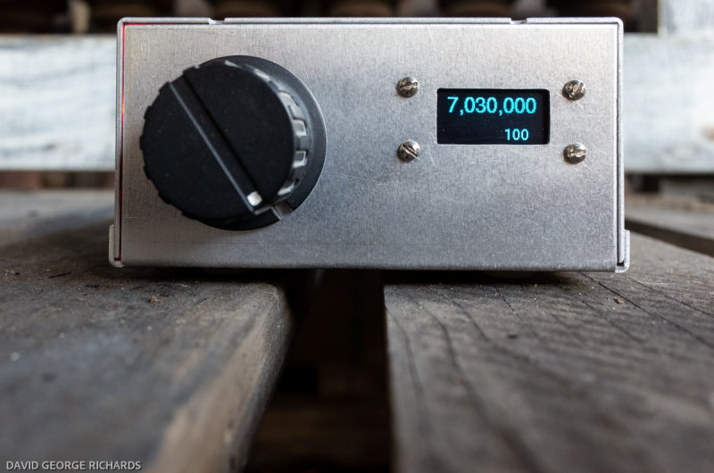
UPDATE (Jan 30th 2021) – I made a few small changes to the sketch, to improve the display a little. I found a font to display the frequency, that is a little larger. It is in the U8G library, and is known as helvB18. I also removed the word “step” from in front of the step size, as I felt it was self-explanatory. The text needed to be moved around on the display a little to fit it in, and this was adjusted in the sketch.
Since building this little clock generator, I noticed that, although the sketch set the Si5351 to start up on 7030KHz, it would nearly always start up 100Hz higher. Unsure whether this is a software or hardware issue, I did the clumsy workaround of altering the sketch to start up on 7029.9KHz. As a result, it now starts up on 7030KHz. I’d like to find the reason for this discrepancy, and fix it at the source.
I also added a 5mm red LED inside the case, with a 1K resistor in series with the +ve lead, connected to the 12V DC power connector on the back. The LED lights up the whole inside of the case, though this is not so obvious in the daylight shot below –
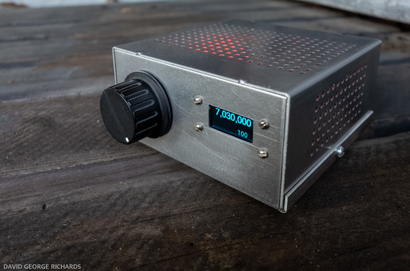
However, when used indoors, the red light is visible through all the perforations in the case, and looks great. It’s almost reminiscent of the old tube days. The red light effect actually looks a bit better in real life than in the photo. This Si5351 VFO/signal generator draws 105mA, of which 10mA is the LED –

Although I’ve had quite a few thoughts about using it as a stable signal source for other projects, it’s very handy to have around the shack, just as it is. Calibrating receivers is a lot easier with this accurate signal source. I didn’t run the calibration sketch but, through a process of trial and error found a correction integer to place in the sketch, that places the VFO to within a few Hz, as verified by beating the output against WWV.

Nice work, Dave.
I took am trying to develop some skill in using the amazing Arduino and the small modern chips like the Si5351a.
I built a simple VFO from a 2015 QST article by W3PM but would like to build one like the VFO that Jason shows in one of his Youtube videos. https://www.youtube.com/watch?v=791NupCbiWU
This would make this old timer very happy.
73, Jack W6VMJ
Jack – I thought I replied to your comment yesterday, but it’s not showing up, for some reason. I do believe the VFO in that video was built by Tom AK2B, using Jason’s libraries. It looks like a great little VFO. I’d like one like that too!
73 for now,
Dave
AA7EE
Dave, you know more about digital things than you let on, I believe 8^) A fine job of your first Arduino VFO. Eloquently and thoughtfully described as usual.
My story is in some ways similar, I deferred tackling this project for more than a year while I got SuperVXOs out of my system. But once I built my first Arduino and si5351 VFO BFO controller there was no going back. I now have about 5 of them around the shack. My realization, like yours, is that what you are building is a controller, the RF clock generator is just a peripheral, albeit a useful one. You’ll be adding band switching, multiple VFOs, s-meters, software AGC, smart dials, SWR monitoring, power management, keyers etc in no time. It’s all just a few lines, or a screen, of code.
How long before we see an Arduino/si5351 based homebrew CW rig all perfectly laid out in your inimitable style?
73 Paul VK3HN.
Thanks Paul. I have little idea where this journey is going to take me, and past experience has shown that sometimes, it comes to a sputtering halt, while I focus my interests elsewhere, and recharge the mental batteries.
Although I pretty much know what I’m doing with the hardware, this experience made me realize that it is only part of the equation. This particular project won’t feel truly complete until I understand the code that runs it, and have either modified, or re-written it from scratch, to exactly suit my needs. I just started reading up on how to write programs for Arduino, so we’ll see where this ends up.
Always something to learn!
73 for now, and always good to see you (in the online sense, of course!)
Dave
AA7EE
I always enjoy your posts and marvel at your Manhattan construction. I noticed a nifty technique you are using to mount the display on your chassis/case which I’ll employ as my previous attempts have been worst than a bad dog’s dinner.
How do you get you copper boards to look so clean?
I’m sitting my UK intermediate ham assessment/exam in two weeks and here is my attempt at Manhattan.
https://w6png.wordpress.com/2018/04/20/80m-home-brew-vfo-for-the-uk-intermediate-ham-assessment/
Paul W6PNG sitting at Heathrow….
Paul – I scrub the boards with a steel wool pan scrubber, dry them, while being careful not to touch the now grease-free boards, and give them several light coats of clear Krylon lacquer spray. I don’t know about the other brands, but you can apply multiple coats of Krylon fairly swiftly, only waiting a minute or two between each coat. Full drying and hardening takes 24 hours, but I usually start building after an hour or two. It takes a bit of practice to get the spraying technique right. If you spray from too far away, the coat of lacquer forms in tiny droplets, and doesn’t give adequate coverage. If you go too far the other way, it forms too thick a coat, and pools. I actually sprayed the coats on this VFO board too lightly. One of these days I’ll get it just right, but you have to learn to accept imperfections in this game, or you’d never get anything done!
I scrape away the lacquer in the places where pads are to be glued, with a small jewelers’ screwdriver, to help adhesion. I also try to rough up the copper a bit with the (old) screwdriver, as well as scraping the underside of the pad with a sharp craft blade, also to help adhesion. Not sure if it works, but it can’t hurt. However, you can solder straight to the ground plane, with no preparation, as long as you have a good temperature-controlled iron. It just melts through the lacquer.
73 for now, and your “new life” in Scotland looks wonderful. I’m quite envious. Enjoy!
Dave
AA7EE
I do exactly the same. My tip… for really sparkling boards find some French Polishers steel wool grade 0000 here in Aus. Use this for a second rundown. It gets rid of the scratches left by the pot scrubbing wool. I’ve even tried cream cleansers, like car duco cut-and-polish — it worked but wasn’t really worth the effort. Then a few light coats of sprayed clear satin enamel. The soldering iron burns thru it in an instant. 73 Paul VK3HN.
Paul – great tip about the fine grade steel wool. Thanks!
Great Stuff Dave…keep meaning to get beyond the blinking LED stage myself but in my case doubly hamstrung by meaning quite hopeless at the analog stuff as well 😳
73 Paul G0WAT
Paul – one thing I have found is that I learn things when I am ready to learn them and not a moment before. I am incredibly resistant to acquiring new knowledge. It’s not something I’m proud of, but it’s the way I am. Every now and again, the time is right, and I actually take a few steps forward, learn a few things, and surprise myself.
It will happen when you’re ready!
It is a good practice to run a piece of coax instead of just a wire from the VFO output to the SMA connector.
Normally I’d agree, but in this case, the required cable run was so short (an inch or less), that I didn’t see the presence of RF around that short piece of wire causing undue interference to any input circuits in the enclosure. If you look back through some of my other projects in this blog, you’ll see that when the cable run inside an enclosure is anything other than very short, I use a length of RG174-U.
I’ve sorta followed the same ideas in building an Si5351 vfo into what will become a QRP transceiver for 20 meters (using a crystal filter from a garage sale SSB CB rig find). I’ve got the same Chinese ebay sourced encoder switch, and a 32×128 OLED from ebay. I’ve used the si5351MCU library, which is an optimized bit of code. One of the chips outputs is the vfo, another is the bfo/car osc. The third output (which is only used when the other two are shut off), is used as a test signal generator, or to drive a freq counter for calibrating the exact frequency of the 5351 25mhz crystal. I mounted both the atmeg328 and the si5351a on breakout boards (the 5351a by itself costs less than a buck from Mouser!), and the I put both boards on a piece of pad per hole perfboard. I ran the atmega at 3.3 volts with an 8mhz clock to avoid needing level converters for the OLED and the 5351. I also provided the OLED with its own 3.3 volt regulator, and put an RF choke in series with the 3.3 volt power to the display. Doing this cuts down the rf noise that these displays can produce (there is enough background QRN on 20 without the rig making its own!). Since the circuit I’m using for the transceiver makes double duty of the rx mixer as a bal modulator, and the product detector as a tx mixer, the vfo and bfo need to be swapped when going from rx to tx. This can be done by just reprogramming the Si5351 to change frequencies for two of its outputs. Design ideas for this rig were borrowed from DK7IH btw.
Dave,
Do you know how the Si531 osc. is turned off in a CW transceiver so the signal is not heard during the reception? Is the power reduced for the CLK signal that feeds the TX? Or is it changed to another frequency? I assume all three CLK signals are used. One for the TX, on for the Mixer in the receive section and one for the BFO.
Jack –
It’s been a while since I built this little VFO, and I never did get very deep into the theory, but I think you can switch the individual CLK outputs off with a line of code. Another possiblity, as you mentioned, would be to keep that particular CLK output running, but move it far off frequency. Hans Summers, in his QRSS transmitters, uses the second approach for maximum stability. With a CW rig, you wouldn’t need the same degree of stability, so I think that switching the CLK output off could work.
However, I am not a good person to ask about this!
73 for now,
Dave
AA7EE
I made another Si5151 based VFO for my old homebrew 144 MHz transceiver, replacing original crystal VXO. http://ok1zad.nagano.cz/kentaur_2018/kentaur_vfo.mp4
73 – Jirka OK1RW
Jirka – that looks great – and I like how the digit that is being adjusted by the encoder is underlined. Nice work!
73 for now,
Dave
AA7EE
Dave-I just stumbled across this project while seeking advice on treating PCB board for cabinets (you ARE THE authority!).
In order to perhaps re-kindle your interest in the Si5351 and such; I would like to share some of the simpler ideas that I have devised. Instead of the complex and fiddly code that is so pervasive, I have managed to simplify some things down to my meager level of understanding. For one, I came up with what I call “Agile Tuning” avoiding the constant punching of the tuning knob and the annoying extra display line for tuning increment. I also avoid the complex (and spread-out) code for the display, keeping it in one simple subroutine. As a result the “sketches” are simple and short.
An example is the EZgen II project found on ND6T.com under “Test Equipment and Tools”. Sketches for transceiver use are under “BITX” in the “Tuning methods and software for the BITX” catagory. It’s all there for the taking. Use what you can. I’m always eager to answer any questions. Perhaps simplified code will get you off “high centered” (as they say in the off-road driving world).
Your projects are inspiring for all of us. We all want to be like you!
73,
Don
This DDS generator solution is only useful for generating clocks suitable for digital circuits!
To have a “good” VFO or generator useful for laboratory use, it is ESSENTIAL to add a series of low pass filters (better still if they are band pass filters) that eliminate the unwanted odd harmonic frequencies of the square wave present in the output.
As it is made, this generator is only a source of INTREMODULATIONS, beats and unwanted signals that disturb the reception and transmission if the generator is used as VFO and BFO or prevent readings of truthful data if it is used as a generator in the laboratory!
As it is built, it NEEDS NOTHING! only to generate odd harmonics of the desired frequency!
Loris – you are correct. It has been a while since I wrote this blog-post and, although I haven’t the time right now to re-read it, I most likely did not note that a low-pass filter will be required, if the desire is to output a reasonably pure sine wave.
On this subject, I have been wondering whether, if a clock generator like this is used in, say, a receiver, whether it’s necessary to filter the clock output of the Si5351 generator, or whether a bandpass filter on the input circuit of the receiver is sufficient.
Anyway, it’s fair comment.
73,
Dave
AA7EE
Quite true if you’re going to use it as the signal source going directly to a transmitter. But if you’re using it as the LO for most of the currently popular types of mixers, including diode rings and H-mode FET and analog switch IC mixers, a square wave is the preferred signal. (You’ll want a bandpass filter at the output of the mixer.) You’ll see a lot of ringing on an unloaded output from an Si5351A, but putting a load on the output should yield something that looks more like a square wave. You could also use a Schmitt-trigger buffer between the VFO and the mixer to square it up more.
I too thought feeding a mixer with square waves was a crime. Then I started studying the designs of K1SWL ( designer of many successful ham kits ) and others. Not so. Look at the K1SWL Hilltoppers and Phaser ( which is selling like hot cakes ) and you will see a si5351a directly driving a 602/612 mixer. Dave explained it all to me and I now see it. I’ve done it on some of my designs too. Works fine.
The 5351a is boon for new designs. You will see it much more. If you are a purest, you can LPF it. I do when I need it. I’m no engineer but I’m following the lead of the pros……
Bob
WA1EDJ
Beautiful design!
73, AD7U
There is a large flaw with this project, and that is the box cover! The soldering and board design are so beautiful it should have a nice transparent case! 🙂
I really enjoyed your post. Very nice work on the project. I built a VFO using the Si5351, and it worked well in my hombrew transceiver. I also built a VFO using the AD9951, but I found that it was far too noisy for my taste. The Si5351 is a great ic for homebrewing. Thanks for your contribution to the art of ham radio!
Stan
Dave,
I’m sure you have had others say what the 100Hz discrepancy on the Si5351 clock is, but I will put my 2 cents in.
Most likely its the crystal frequency error and you are right to offset this in code. I have a few boards I have done myself and they all have different crystal frequency offsets. I have in my code a mode where the end user can select an offset to ‘tune’ the si5351. Once its on the it will pretty much work for the entire frequency range.
You need a freqency counter or radio though to configure
73 W8ZLW Jeff
Hi Dave,
In using the SI5351 VFO in your VE7BPO Mainframe receiver, what IF frequency did you use/ input in the sketch?
You’re site is a really great resource for us newbies!
Thanks,
Sonny
Hi Sonny –
I entered an IF of 0KHz, as with a direct conversion receiver, the VFO is directly on signal frequency. Incoming RF is converted directly to baseband audio. There is no intermediate frequency, so we enter zero.
I’m glad you’re enjoying the posts!
73 for now,
Dave
AA7EE
I see what you have done! Thank you for scribing the entire process. In fact, I followed your article to try out SI5351 with my Arduino Nano. Anyways I wrote this on my blog. Check it out please
https://itshamradio.com/amateur-radio-codes-for-si5351/
de VU3HZW