
Back in May of this year, Sheldon N6JJA began sending me information and details of his version of N1BYT’s WBR regenerative receiver. It went through several iterations, before ending up at the final version as shown here. Even this version is still a work in progress – as all good products of experimentation are. Sheldon took the original WBR circuit, as described by N1BYT, and made a few changes. Firstly, he added a preselector. Regens are well-known for having poor strong signal performance. A pre-selector can’t help with very strong signals close to the received frequency, but it may well help to protect the fragile front end of a regen from very strong signals away from the frequency the regen is tuned to. Secondly, a tunable preselector is a very handy tool for anyone who is experimenting with simple receivers, whether direct conversion, regenerative, or simple superhets. It could be well worth building this as a separate unit, for future use and experimentation. Of great interest also, are the changes that Sheldon made to the classic WBR circuit. He describes them in some detail in this article. It makes for a good read, and may encourage you to try building it for yourself. If you do, please let me know how it goes, as I haven’t built this version of the circuit yet.
Sheldon, amazingly, found enough time away from his very busy silicon valley job, and responsible position as a first-rate cat dad, to write up this project as a complete article. Rather than attempt to interpret his words and re-write them in my own style, I’d rather that you get all this great information straight from the cat-dad’s mouth so, without further ado –
(Oh, one more thing – check out the way he draws his schematics. Accurate and beautiful!)
How it started (by Sheldon N6JJA)
In 1957 I was in second grade in a small town in rural Illinois. Our “library” was a bookmobile that came through once every two months. But even that long ago I was completely in love with all things radio and electronic, so when Alfred P. Morgan’s book The Boy’s First Book of Radio and Electronics appeared I checked it out and devoured it over the next two months. For me, the centerpiece of the book was a design for a simple, one-tube regenerative receiver. My desire to build such a thing knew no bounds, but a lack of money and parts made it a non-starter at that time. I became a ham in 1965 and my attention turned to more modern equipment and kits to build things, but I never got over that old regen. Fast forward eight more years and I’d gotten my hands on my first “boat anchor,” an SP-600-JX7. Alas, I was once again in love, but the radio wasn’t mine to keep, and I again resolved, “Someday…”
Oddly enough, that’s all part of how and why the WBR-Oscar came to be. Over the past few years I’ve been buying and restoring a variety of “boat anchors,” and now have a lot more than I can keep. And that radio-crazy second-grader wound up with a Ph.D. in electrical engineering and a huge junk box and some decent test equipment. So, somewhat naturally, my first major project last year was to build something to help those old radios perform with a little more pizazz. It started as a wide-range antenna coupler, then added a preamplifier that became also a preselector, then added an audio amplifier, then a DSP filter…well, you get the idea. One of our cats, Oscar, helped me with all of this, making sure that now parts got included that hadn’t been checked for obedience to the laws of physics, particularly gravity. As you can see in Figure 1 below, Oscar became the name of that “helper” unit. Oscar sits proudly atop his namesake.

I considered, for my next project, that one-tube regenerative receiver. But then, along the way, I came across an article from QST from August 2001 for a regen that I’d started to build but never finished. (Life gets in the way sometimes.) The article was by Dan Wissell, N1BYT, and titled “The WBR Receiver.” (Citation at the end of the article.) Rummaging through my collection of parts I decided that this was the right project at the right time. Mr. Morgan’s radio would wait a bit longer, but my desire to build a regen was finally going to be fulfilled.
Over the years a lot of these receivers have been built, and the results have been mostly good, it seems, even spawning a lot of designs based on the WBR detectors but without the WBR tank circuit. Lately, thanks to the ongoing blog of Dave Richards, AA7EE, interest in this design has been renewed and some of the design’s deficiencies noted and, to a certain extent, addressed by experimenters. Now, however, buoyed up by the information in Dave Richards’ blog and some other QEX articles, I decided that it was time to put my own spin on things and see how far I could push the design. The result is the WBR-O receiver, and it now covers, fairly easily, 6 to 15.6 MHz with a single tank circuit, making it now a true “40-30-20” meter amateur and SWL radio. As an additional feature, the “O” (for Oscar) part refers to a preselector/preamplifier that both isolates the input of the WBR circuit and adds front-end selectivity and some amplification. The preselector/preamplifier actually tunes from 80 to 10 meters (in two bands), includes widely adjustable gain, and can easily be built as a stand-alone for folks who only want that part. The photo in Figure 2 shows the pair as built.

The design you see in the photo is actually the culmination of months of work and numerous revisions and tweaks. Some things helped, some didn’t, but I learned a great deal along the way. I also, on purpose, used several “lousy” construction techniques to convince myself that, simply, “If I can build this, anyone can build this.”

This article is broken into two parts. First comes the “Oscar” preselector/preamplifier. As I said, I intended it to be either part of the overall receiver or used as a standalone where desired. The second part deals with the WBR upgrades. Both designs were built using the same techniques and I’ve tested both and found that—especially in concert—they do about as well as some of my boat anchors! So if your soldering iron is ready, I’ll start by describing “Oscar.”
Part 1: Oscar’s Preselector/Preamplifier

Figure 3 (above) shows the circuit during testing on my bench. To the left I placed the coils, clustered around a small relay (Panasonic TQ2-12V). To the right is the amplifier portion of this circuit.
Figure 4 (below) shows the schematic.

Now before you say to yourself that it looks pretty complicated, let me point out how simple it really is. Each “band” has its own bandpass filter that it tuned by one or more Toshiba 1SV149 varicap diodes. The 1SV149 is a little gem that was developed for AM radios but is now obsolete. In spite of this, that diode is plentiful and inexpensive on the internet (I got mine from eBay, about 50 for $10, but Amazon sells them, too, as does Minikits.com.au.) An important item to note here is the value of the series isolation capacitors for the diodes, C1 and C3 in Fig. 4. I use 0.1 μF, 50V ceramics with an X7R stability rating. The large capacitance is actually a must; as the value goes down, the interaction between those caps and the rest of the circuit becomes a problem. The relay is something that I had in a drawer, and made the layout a bit easier. I’ve also built “Oscars” using rotary or toggle switches to switch bands, by the way, so while the relay is nice to have, it isn’t required. One thing to note, however, is that, with the relay, the overall design lends itself quite nicely to a remotely-tuned preselector that can be mounted right at your antenna. So far, nearly everything I’ve built along these lines has worked. The amplifier in Fig. 4 is based on a low-noise MMIC pair in a push-pull arrangement that keeps distortion and unwanted harmonics down a bit. The MMICs are Mini-Circuit Labs MAR-6SM+ devices. At a maximum of 16 mA per device they offer gain of about 20 dB and noise figure around 2 dB. Quite impressive for so simple a device. The 1:1 transformers are also from Mini-Circuits, their T1-1+. All of these components offer good technology for a relatively low price. The relay (from Digi-Key, for example) is $3.88 in small quantities. The MAR-6SM+ is $1.40 each, but the minimum is 20, so either consider a lifetime buy for $28 or split the batch with a friend. The T1-1+ is $3.25 in small quantities. If you’re up to it, go ahead and wind your own transformers on small type 43 ferrite toroids. A simple bifilar winding should work, and there are usually design guidelines in articles on baluns and transformers to help you decide on a target inductance. Actually, I found that building my first “Oscar” made me make sure I had enough parts—including transformers—to build more of them. The circuit has become somewhat my “go-to” front end for things. I should add that I’ve also built the amplifier section with a single MMIC and without the push-pull transformers, and it still works okay, if you want to minimize or simplify things. The circuit then looks more like the C5-U1-C6-R6 cluster in Fig. 4.


Table 1 (below) gives my winding data for the toroids, including those for the WBR receiver part. I like the website toroids.info to help me design the coils, then I use another best friend—a Peak LCR45 meter to verify results. I find that, even knowing that each time wire passes through a toroid counts as a “turn,” I wind up removing a turn or so once I measure things. Frankly, this whole project would be a lot more difficult without the LCR meter, and once you use something like this I suspect you’ll be hooked as well. The bandpass filters don’t do nearly as well if the coils aren’t either the correct values or reasonably well matched.

Good thing to remember: the MMICs and diodes are sensitive to ESD. Not horribly sensitive, but you will want to be careful, since it will save you headaches later on. Sometimes working on some aluminum foil or an inexpensive ESD mat is plenty, also making sure you touch the foil or mat before handling a part. Overall, in my own experience I’ve found these parts to be pretty robust.
Depending on the available PCB space you have, you might want to experiment with the general layout on perforated PCB material and then make a sketch or photo of your final design to guide you in construction. Part of the fun of this project is that we all tend to do things differently and put our own “fingerprint” in the final result. Remember, although I’ve done a lot of up-front work to guide you, what you build will be your own to be proud of.
My own usual RF build technique is to use 0.10” center perforated PCB material with plated through holes and cover one side with copper foil tape to make a ground plane. The boards I used in this build are 7 cm x 9 cm, and as you can see, I have plenty of room. (I should also add that the last revision of the WBR was done on a board about half the area.) Then I use an Exacto knife (or something like that) to carefully cut away portions of the ground plane where necessary. Figures 5 and 6 show this in more detail. Then I use tweezers and solid wire-wrap wire (28 or 30 gauge, stripped first as needed) for the interconnections. I solder components to the PCB and leave about ¼” of lead projecting on the underside of the board to provide for the interconnections. These are made using the tweezers (and maybe a magnifier) to wrap wire on one lead, anchor it with solder, and next do the same at the other end. (I call this “Compact Wiring.”) This keeps the wiring neat and compact and still provides an excellent RF ground. However, to be honest I’ve also used “dead bug” and even less glorious methods of construction (even using longer wires), and just about everything works as long as you’re careful.
Mounting the MMICs is the only thing where I needed to think hard about “how to do it.” In Fig. 6 you can see the MMICs, mounted on the ground-plane side (the “underside”) of the board, but mounted “upside down” with respect to the photo. I drilled a hole in the board for each MMIC, just large enough for it to rest in the hole, allowing the protruding pins to just touch the adjacent plated through holes and allow me to make good electrical connections.
Turning back to the schematic, you’ll notice that I use small voltage regulators to keep things stable and quiet. The LM317LZ is an inexpensive part (about 40 cents apiece from Digi-Key) that can handle up to 100 mA of load. U3 is used to provide the tuning voltage required, and U4 controls the gain of the MMIC amplifier by varying the voltage presented to the current-limiting resistors feeding the MMICs. I’ve taken to using these ICs in virtually every project. They simplify the design work and are very flexible and stable. Add to that, they offer some low-pass filtering effects that can reduce the hash from cheap power supplies. No miracles, but good engineering.
I recommend coaxial cable input and output for this circuit. I bought a bunch of PCB-mounted SMA connectors a while back, and you see them in Fig. 3. But there are so many different ways of making these connections—especially if you choose to do the switching via a panel-mounted switch—that no builder should be intimidated by the technology.
I used a 10-turn pot for the tuning and a single-turn pot for the gain. Both are linear in design and do not need to have a wattage rating over 1/4W. But a word about choosing potentiometers. I’ve used cheap ones from the Pacific Rim and higher quality ones from US suppliers. In my experience, especially in the tuning pots you tend to get what you pay for, although the cheaper ones can be used if you are careful how hot they get during soldering. It seems that the inner workings of the less expensive ones are more susceptible to heat and can “quit tuning” if you do a lot of “cut-and-try.” If you do buy the cheaper ones, buy several.
Results
Figure 7 shows my measured results, using a Rigol DSA815-TG spectrum analyzer and subtracting the tracking generator output level. That means that the circuitry was tested with a good, solid 50 ohms input and output, but the circuit still works well in my shack with antennas not very well matched. The bandpass curves were taken with a “gain” setting of about 10 dB. As you can see, the curves are sharper on the low end of each band, but there’s also more attenuation there, about 4 dB less on the low band, and about 5 dB on the high band. The sidebar on “Designing your own Oscar bandpass filters” talks a bit about this, but once you start designing for Q values above about 10 these effects are normal. But a preselector that maintains Q over 10 over this range should produce a workable unit that provides some selectivity without having to constantly readjust things every time you change frequency by a couple of kHz.


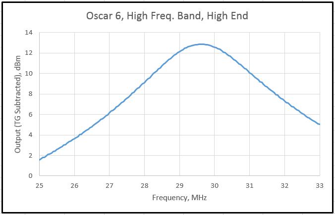

At the bottom of Fig. 7 is the gain range curve at 14 MHz. With the design as I’ve built it, I can bias the MMICs to be “just barely there” and provide some signal reduction or to blast things with an additional 15 dB or more.
Now I chose to do this in 2 bands, but you may decide on 1 or 3 or anything else. The MMICs don’t care, as long as they think they’re seeing roughly 50 ohms at input and output. But be aware that the MMICs also will amplify anything from DC to 6 GHz! Using them without some form of bandpass in front will suck the amplification headroom from where you want it to someplace you don’t. And if you decide to make things simpler, using a single MMIC is a straight-through configuration works very well also. I’ve tried a lot of different configurations, so these are just my guidelines based on experience.
About all that remains is to hook this circuit up to a receiver and see what happens. Don’t be afraid to experiment. The fun of building something like this is that there’s a lot of room for changes, improvements, and growth. For instance, the gain section in the Oscar design is custom-made for a homebrew AGC circuit, and maybe someday I’ll give that whirl. (If you don’t beat me to it!) The next part of this article will expand on what I’ve written here to build the companion WBR receiver, but I’ll also refer back to this design to cover some of the construction guidelines I’ve mentioned here.
Part 2: The Upgraded WBR Receiver Design
As I mentioned in the beginning of this article, both the Oscar preselector/preamplifier and the upgraded WBR receiver are designed to work together or be built as stand-alone units. Figure 2 shows both units assembled with standoffs between them right before integration into a chassis that has been the final home for all the previous design iterations.
So what’s changed? Well, if you look at the schematic for the RF deck in Figure 8, it might seem that not much has evolved since N1BYT’s article back in 2001i. However, a lot of tests and calculations led to some significant changes. But rather than just list the changes, let me take you on a brief excursion as to why they were made.

Online blogs and chat lines have talked about different variations on the WBR theme for a while. Often there are a few things that everyone seems to agree on, like the fact that AM sensitivity is very low and that the near-zero input impedance is needed to block strong signals, and that it’s difficult to get more bandwidth out of the design, even if mechanical tuning capacitors are used. Sometimes it seems to be nitpicking, but I decided to dive in and see how much pizzazz I could give the basic design.
First, about the sensitivity. The WBR isn’t a “normal” regenerative detector design, and this gets overlooked sometimes. It’s actually a regenerative Q-multiplier with an infinite impedance detector (IID). When the Q-multiplier is oscillating, the available signals to the IID are quite a bit stronger than when the Q-multiplier is set just below oscillation threshold, as in for AM reception. But look at the IID part of the circuit. It’s actually a source-follower and thus offers little chance for any amplification. IIDs have been around in tube circuits for years, favored by AM aficionados for their excellent low-distortion detection characteristics. So when you’re trying to listen to AM signals, you’re going to need a fairly good audio preamplifier. That’s Q3 in Fig. 8. I’ve looked at a bunch of WBR-like circuits online, and there are several good (and not-so-good) preamplifiers to consider. In the end, I designed my own. It has pretty good gain (about 120-150) and doesn’t use parts that aren’t easily available. I should mention that the value of C12 is important, though not critical. I use a rather large capacitor there, 100 μF, and that really helps keep the gain up over a nice audio range. Probably anything over, say, 47 μF should work.
Next, the “front end,” or lack of it. There are 2 points to make here. First, that’s why the Oscar preselector/preamplifier became part of my own design. Second, that 1” piece of wire in the original design by N1BYT helped “balance the Wheatstone Bridge,” but many builders have fiddled with that, adding a little inductance at that point. I tried that too, but finally got an idea that worked better. It’s a simple single-turn link immediately adjacent to the L1 center tap (which is connected to that 1 to 1.5 inch wire to ground). Feeding the 50-ohm sourced signal in through that tap turned out to be about a thousand times better than the “old” way. (See the addendum for technical details.)
I spent a lot of time working to get the design to work reliably over the roughly 10 MHz span that it finally achieved. The capacitance range of the Toshiba 1SV149 varicap diodes really did shine there, but early attempts to tune below about 8 MHz weren’t successful. In the end, though, what’s in the final design will probably tune below 5 MHz if I spent more time on it (and maybe even cover 80 to 30 meters or something like that). That’s where a lot of changes found their way into the design, but let me talk about them individually.
First, I was initially using garden variety (i.e., “flea market”) 2N3904 transistors for the Q-multiplier. Frustrated at the limited tuning range, I first increased the “gain” of the oscillator by increasing bias voltages from 5 volts to 12 volts. That helped, but not enough. In the end I found that the hFE for that transistor (i.e., its DC gain) is vitally important. My weak oscillator used a 2N3904 with hFE of about 85-90. I found a first-quality one with gain closer to 180. Aha! Much better performance. I got down to about 6.5 MHz at the low end.
But, to make a long story much shorter, I found an excellent, and even better, alternative. It’s the BC546CT from On Semiconductors. At about 10 cents apiece (about the same as the 2N3904) it offers the same basic qualities of the venerable 2N3904, but with an average (sample of 40) hFE of 553! A batch of first-quality 2N3904s had an average hFE of only 189. The pinout is the opposite of the 2N3904, but otherwise it was just a drop-in and now there’s no trouble with making a Q-multiplier that will oscillate easily just about anywhere, and I don’t have to measure hFE endlessly to find a winner.
One experiment that also helped was to try different values of C2 and C3. You see, the feedback network in this oscillator (that’s the basis for the Q-multiplier) works fine for some values of C2 and C3, but as the frequency goes down, the losses in the feedback loop go up and can prevent oscillation. Dropping C2 and C3 to about a quarter (to 100 pF) of what I used initially (330 to 390 pF) did the trick. I’d recommend using small ceramic caps with an NPO or COG stability rating. Pushing this oscillator down further in frequency might entail re-tweaking those capacitor values, but that’s just part of the fun. One additional benefit from using the small capacitance is that the amount of regeneration bias required over the whole frequency span stays much more constant that when using the “older” values. Oh, and one last thing: in the original design the base of Q1 was biased using a more classic resistor pair, one carrying regeneration voltage, the other to ground. I removed the one connected to ground. What you see here works much better.
Now for my secret weapon. The little trimmer capacitor, C4, is unusually important. After staring at the original schematics for hours it occurred to me that the “balance” sought is almost impossible with the components used, no matter how carefully one measures things to force it to happen. Once I get a circuit oscillating, I tune to the low end of the frequency band and find where regeneration quits (you can hear it in headphones), even with maximum regeneration bias. Then I slowly tune C4 and make sure I have the headphone volume way down. Maximizing the oscillator strength with C4 is a set-once-and-forget adjustment, but it overcomes the last hurdles to giving this design its performance. Any trimmer that is small enough to fit and covers the 50-80 pF range should work. It just has to be near twice the value of C7 to be effective.
All That Bandwidth Presents a Problem
One thing became clear when operating this receiver. Even a 10-turn tuning pot made things dicey. I even found some Bourns “Digidial” counters on eBay and they helped, but not enough for this much bandwidth. I also played with several “bandspread” ideas using two tuning pots before deciding that instead of a bandspread control I could split the tuning range into, say, 6 pieces (I had a DP6T switch). This feature is included in Figure 9 along with the audio section built along with the RF deck. Again, I rely on the LM317LZ regulator, here in a paired arrangement, to set the ranges over which you can tune. Now signals are easier to separate, even with the smallish knobs on 10-turn counting dials. But taking this feature one step further (I encourage you to consider this), a builder might want to skip the “shortwave radio” aspect of the design and adjust the tuning ranges to cover only the 40, 30, and 20 meter bands, a very easy thing to do.

Table 2 lists the resistor choices I arrived at, both for the “shortwave” and “amateur-only” versions. I’d caution you to be prepared to build first and add resistors later. Your circuit might want resistance a little different from mine (and yes, small trimpots would make this a breeze).

Building It and Operating It
As you can see from the photos, the WBR section uses the same build technique (“Compact Wiring”) that the Oscar unit does. I encourage any builder to feel free to experiment with how the layout comes together and how the wiring gets done. What I’ve shown here is just my own way of doing things. Keeping the RF wiring reasonably short is a good goal, as is providing a good ground plane. Apart from that, all the versions I’ve built work (as long as I don’t forget a connection!), so there’s plenty of room for personal variations.
Figure 10 shows everything in my “WBR-O” box. You might note how the box has extra holes and knobs that are leftovers from all the previous versions. I included the ubiquitous 1k pot at the antenna input, but in hindsight, it isn’t needed when I use both circuits. I also decided to use a small 12 volt supply that fits in the underside of the chassis. It’s a good quality and lacks the persistent hash that some cheaper supplies produce. Right now I’m using a Delta PMT-12V35W1AA from Digi-Key. Small, quiet, safe, and at about $15 for a universal AC input it’s a bargain, really.


I’d recommend a 10-turn pot for the regeneration control. Regeneration at low frequencies is higher, dropping somewhat as you increase frequency. You’ll have to develop a feel for this adjustment. With the new biasing I’ve included, it might be possible to use a single-turn pot, but that’s just one more experiment for the future. The key thing when getting started with a regen is that you want as little regeneration as possible. I still have the bad habit of leaving it too high then wondering why things don’t sound right. Overbiasing the Q-multiplier just adds distortion, and even harmonics. Regeneration also varies the frequency a bit, so tuning in on a single CW station, for instance, will require a little practice, but in the end it becomes second nature.
Table 3 lists a few of the more critical parts and their Digi-Key part numbers. Although I use Digi-Key as a supplier in a lot of the electronic work I do for a living, they are also quite amenable to serving the needs of individuals as well. The same can be said for Mini-Circuits and Amidon. Prices are reasonable and you get to choose the quality you can afford.

All that being said, the final product was gratifying to use. Just about anything one of my other older high-quality radios can hear can be heard by this little gem. Of course, selectable selectivity, a noise blanker, and good AVC would help, but…that’ll come later, I think.
With all the changes I’ve made the one ingredient I hope I have added most of all is flexibility. The real possibilities of what this basic design can do have only been barely touched. I think it would be excellent, for instance, to see how small one can make the entire unit, so it fits into camping gear or such. Also, why not 2 oscillators (sharing the same tuning voltage) instead of one, and use the second to drive a small transmitter? Or a second oscillator to drive a frequency counter so you can actually see where you’re tuning? Or using what I’ve explored here on other designs, like AA7EE’s “Sproutie” regenerative? Or add some good audio filters? Or, as I said before, adding AVC via the gain control voltage on the Oscar circuit? Or…well, you get the point. This is definitely not a software defined radio, but an imagination defined radio, and, as Oscar would note, perched high above me on my equipment, the sky’s the limit.
—–
Sheldon Hutchison, N6JJA, has been a licensed amateur on and off since 1965 and currently holds an Extra ticket, a Ph.D. in Electrical Engineering (University of Illinois) and is an ordained Episcopal priest. He and his wife Eileen, KI6UZJ, live and work in the Silicon Valley with their cats, including Oscar and several other “helpers.” Dr. Hutchison works in the laser industry (while also a retired but active priest) and Eileen is employed in the Valley’s aerospace industry. An avid experimenter, Dr. Hutchison also enjoys restoring old “boat anchor” receivers, and currently—according to Oscar—needs to find homes for a few of them to give his helper more room to play.
i Wissell, Dan (N1BYT), The WBR Receiver, QST, August 2001.
ADDENDUM
File this under “Can’t leave well enough alone.”
There’s something in electromagnetics called “reciprocity.” Basically, it means that if signals get into an antenna or circuit efficiently, they get out just about as efficiently. Taking long walks at noon helped me find ways to use this phenomenon. For my “Oscar” receiver I found one. I’ve long used my spectrum analyzer, clipped to the low-impedance tap on L1, to indicate the health of the regenerative Q-multiplier by making it oscillate and observing the relative strength of the signal. Well, in the schematic below I experimented with adding a link right next to the low-impedance center tap of L1 as a way of improving coupling to the Q-multiplier from a 50-ohm source. Compared to the previous way of coupling to the center tap the signal measured on the spectrum analyzer shot up by 30 dB! Adding 2 turns is too much. Moving the link too far away from the tap makes oscillation much more difficult. And after adding the link, you’ll want to go back and re-tweak C4. The photo also shows the red wire link as I installed it.
Now Oscar’s even happier.


Beautiful presentation of your work.
Robert – just to clarify, this is Sheldon N6JJA’s work. He has done a great job with his WBR.