
This is one of those projects that has been residing in my head for a long time, as something I wanted to build. I’ve always liked direct conversion receivers. With them, as with regens, I felt that they have been underestimated by many builders and hams as being novelty items. Their apparent simplicity can also be their greatest downfall. Because, in their basic form, they often have few components, they can be “thrown together quickly”, in an evening, by a novice builder. That, of course, is where the problems start. The high degree of audio amplification necessary in a DC receiver lends itself to microphony if certain types of coupling capacitors are used (ceramics are prime candidates, for example). Long, stray leads help to pickup hum, especially if they are in the earlier stages of the amplifier. Dead bug and Manhattan construction are very worthy methods of fabrication, but leads must be short and stout, especially in the parts of the circuit where it matters the most. Free-running LC VFO’s can add microphony if not solidly built. If the VFO is running on signal frequency and not adequately isolated from the later stages of the receiver, unwanted feedback loops can form.
For the above reasons (and more), some builders put a DC receiver together, twiddle around with it a bit, then toss it aside, thinking of it as merely a “fun project”. I think they can be more than that. In fact, I know they can be more than that, from experience, as does Todd (aka Professor Vasily Ivanenko), one of whose direct conversion receivers is the subject of this post.
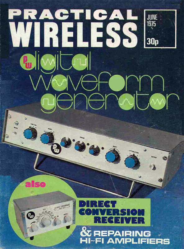
As a kid, I spent countless hours gazing at a little direction conversion receiver project designed by R.H. Longden, in the June 1975 issue of Practical Wireless. It used a 40673 MOSFET as the mixer, and worked on both the 160M and 80M amateur bands. I never did build that receiver, but it wasn’t for lack of desire. I’m surprised I didn’t stare a hole right through the paper, so much time did I spend fixating on it! I was 11 years old when that issue came out, and I suspect the reason I didn’t build it, was partially lack of funds, but mainly lack of relevant experience on my part. It would have been a very involved and complex project for me at the time. Had I attempted to tackle it, I think there would have been a very high chance of it never working. Instead, I just gazed, and gazed, and dreamed about that little direct conversion receiver for top band and 80M –
Quite a few years later, in March 1983, a direct conversion DSB transceiver for either top band or 80M (your choice), was described in the pages of Ham Radio Today magazine by G4JST and G3WPO. A kit was available. By then, I was older, and a slightly better builder. I assembled the board, installed it in a case, and was overjoyed to discover that it actually worked! Paul G3UMV, who lived a mile down the road, heard me on 80 and, probably curious to see how a kid had made it onto 80M with a homemade rig, came over to ‘ave a gander at the rather messy creation that I had stuffed into an aluminum project case. The DSB80, as it was called, was based around a Mini Circuits SBL-1 diode ring mixer package. A free-running LC VFO, tuned by a polyvaricon, was coupled into one port of the DBM, while an antenna, via a double-tuned bandpass filter, fed the other input port. The IF output of the SBL-1 led to a simple diplexer, which fed a high gain audio amplifier. I had also constructed a simple active audio filter with 2 switchable bandwidths, to enhance the listening experience. I spent many happy hours tuning around and listening on 80M with the DSB80. It was this first experience that cemented my affinity for direct conversion receivers built with commercially available diode ring mixer packages. It just seemed so simple – you squirt RF into one port, a VFO into the other, and (after passing the result through a diplexer) amplify the heck out of the result. The seeming simplicity of the process of converting RF directly to baseband audio has held great appeal for me ever since. Unfortunately, that project didn’t survive. One day, in later adulthood, in my apartment in Hollywood, I reversed the polarity of the 12V DC supply and, discouraged at it’s subsequent refusal to work, tossed the whole thing away. Now, I cannot quite believe that I did that, but it was during a long period of inactivity on the ham bands, and complete lack of interest. If only I could go back, and not have thrown it into the dumpster of my apartment building! Hollywood is ridden with recent notable history. My little double sideband transceiver met it’s unfortunate end just 100 feet from the spot where Bobby Fuller, of The Bobby Fuller Four, was found dead in his car, in 1966, the subject of a mystery that is still unsolved to this day. The death of my little DSB rig was a lot less mysterious. To think that I heartlessly tossed an SBL-1 mixer into a dumpster, is a mark of how far I had strayed from my homebrewing roots, forged in a little village in England. Now, a few years later, in a city known for it’s sin and excess, I had cruelly ended the life of a stout and honest diode ring mixer. I suppose I should spare a thought for the polyvaricon but, well, you know – it was a polyvaricon! Some years later, I came across a fellow ham, Richard F5VJD (also G0BCT), who had also reversed the polarity of the 12V supply to his DSB80. Unlike me though, he hadn’t committed his rig to a sad and untimely end. He very graciously sent me his unit, which I revived, and installed in a new case.
Commercially manufactured diode ring mixer packages have the advantage of high dynamic range, over other mixer arrangements that use active devices. To me, an SBL-1, ADE-1 or similar, just looks like a virtually guaranteed-to-work DC receiver in a little box. It’s the heart of the receiver, all manufactured for you. You don’t have to bother with diode matching, or the overall symmetry of the circuit. It’s all done for you. Just add a VFO, diplexer, audio amp, and go!
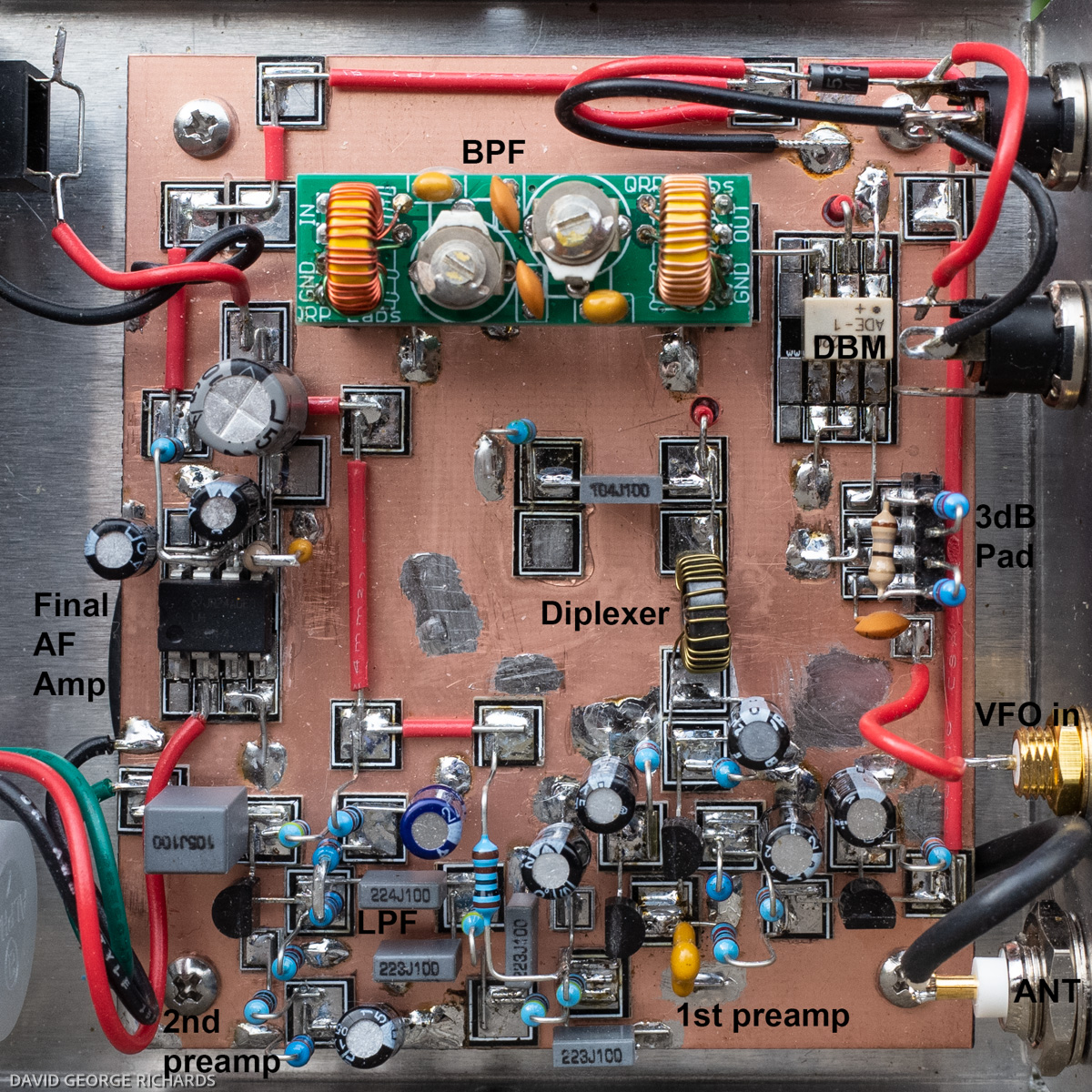
A few years ago, a very generous friend gifted me an assortment of parts for experimenting and building with. Among them were some quality 3.3mH, 10mH, and 100mH inductors. I guessed that his intention was that I would, one day, use them in a diplexer. This is where Todd VE7BPO’s first QRP Homebuilder site comes into the story. On his information-packed site were details of what he called a “Popcorn Direct Conversion Receiver Mainframe” His popcorn approach, if I’m remembering this correctly, referred to the practice of employing moderately-priced, widely available parts, and using them to achieve good performance in his circuits. The mainframe moniker referred, I am guessing, to the fact that the circuit he described was the “meat” of a direct conversion receiver, requiring only the addition of an outboard VFO and a bandpass filter on the antenna input, for the frequency band of interest. The “mainframe” provides the rest of the circuitry.
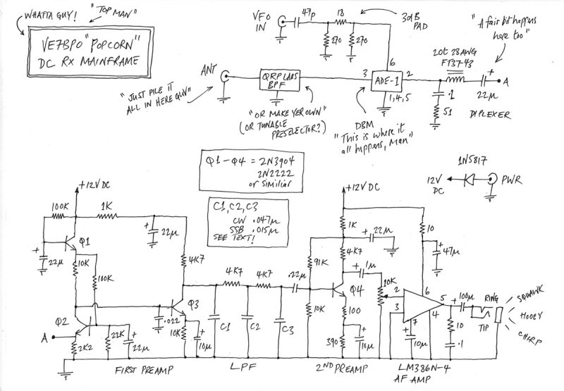
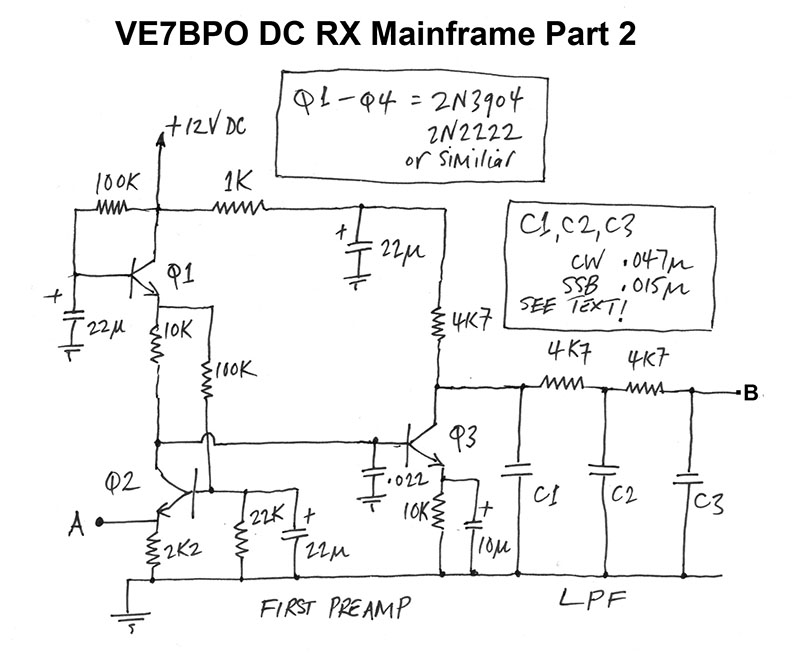
Ideally, I would have liked to have broken a DC receiver into every single component stage, each one individually housed in it’s own case, connected to the other stages of the receiver via cables running between the various boxes. This would allow me to try different configurations and receiver stages, for the purposes of comparison. However, this would have resulted in more boxes and interconnecting cables than I wanted. Experimentation and optimization, though very worthy goals, were trumped by my desire to end up with a convenient and very usable receiver. I decided to build the mainframe with an ADE-1 mixer, and one of the better diplexers suggested by Todd. As it happens, the better diplexer that I chose didn’t work, for some reason. More on that later. I ended up with a less perfect, though very functional diplexer, which is shown in the circuit below. WordPress doesn’t seem to display images as large as it used to, which can make reading schematics a little problematic. I will show the whole schematic first then, for ease of reading, break it up into 3 separate and larger parts. If you’d like a larger version of the entire thing, drop me a line, either in the comments below, or via email (I’m good in QRZ) –
If you have any interest in building this receiver, I strongly recommend checking out the article on VE7BPO’s old website. His new QRP Homebuilder site is in a blog format, whereas the old one was a regular website. He had some issues with hosting, and took it down, though not before archiving it to a single PDF, and making it available to anyone who wished to host it for download on their sites. I won’t give the direct url here, but a quick Google search on Todd’s callsign should get you to the download link. If you have trouble finding it, drop me a line, and I can give you a download link to the file on my Dropbox account. It is well worth having a copy of Todd’s old site, to aid and inspire you in your homebrewing pursuits. Plus, his schematics are easier to read than mine.
Here’s the schematic broken up into 3 parts, which will hopefully make it a bit easier to follow. First, the antenna input circuit, double balanced mixer, and diplexer. Much of this section is block diagrams. If you don’t want to use the BPF from QRP Labs, you can build your own, using the circuit and component values on their site (link a bit later) –
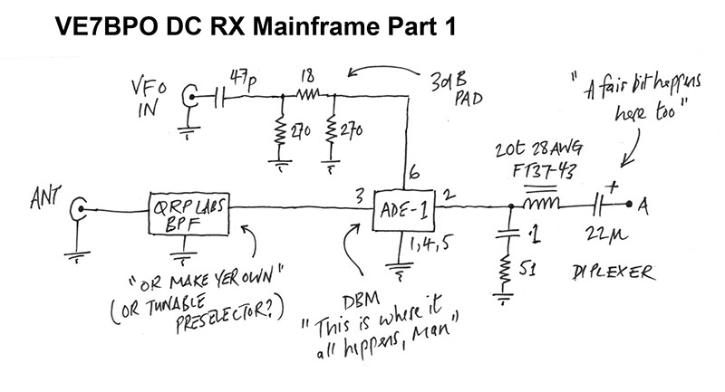

OK, some notes and general guff about the above circuit. For a VFO, I used the Si5351 circuit I put together a couple of years ago. The ADE-1 is a level 7 mixer, meaning that it requires a drive from the local oscillator, of ~ +7dBM. I have read that the Si5351, at full output, develops +10dBM into 50 ohms. Unfortunately, my oscilloscope is not working too reliably, so I don’t have the means to measure this. I decided to incorporate a 3dB pad into the circuit to reduce the output from the Si5351 “VFO” to the +7dBM level (if indeed, it is putting out +10dBM). The pad resistors are soldered onto a header strip that plugs into the board, allowing the builder to easily change the level of attenuation, if required. Room for experimentation and modifications in the future.
The bandpass filter is one of the BPF kits from QRP Labs. These little bandpass filters plug into header strips on the DC mainframe board, making changing bands a simple matter of plugging in a new BPF board. The Si5351 VFO works all the way up to 160MHz according to the specs – and beyond, if you’re willing to accept that it is out of spec when in that territory. It would be interesting to see how this receiver does on the 6M and 2M bands. I imagine a preamp would help.
I didn’t take any photos of the board during construction, I’m afraid – only when it was finished. I began building, as I always do, with the final AF amp, and worked my way backwards. This is a good way to build, as it is easy to verify correct operation at every stage of construction. If you don’t have a signal generator and oscilloscope to inject a signal of known characteristics and amplitude, and verify that each stage is operating as expected, you can still do qualitative tests, with fingers, metal screwdrivers, and a general sense of what sort of sounds should be coming out of the speaker as each successive stage is added. As usual, I pressed Rex W1REX’s wonderful MePADS and MeSQUARES into service. To mount the BPF header strips to the board, I cut an 8 pin DIP MePAD in two, and used one half at each end of the BPF. A few of the Small MeSQUARES, known as Mini Stix, were used where needed.
The final AF amp is an LM386N-4 in it’s default low gain mode of 26dB, representing a voltage gain of 20. It’s a very pleasant part when used this way. Pins 1 and 8 are left gloriously undisturbed! I made 2 small changes to Todd’s circuit here. The first was the addition of a 10uF bypass capacitor from pin 7 to ground. If your power supply is clean, you may not need this. I noticed a reduction in general noise and hash on connecting the capacitor, so left it in. Some circuits show a 0.1 uF or similar value capacitor in this position, for RF bypass but, according to the datasheet, an audio bypass cap was clearly intended. There is a chart in the datasheet showing different degrees of power supply rejection, for different values of pin 7 bypass capacitors, from 0.5µF, to 50µF. You may not need it right now, but who knows what power supply you’ll be using in the future, or what environment you’ll be operating in? 10µF electrolytics are cheap, and easy to add. Even better, try it yourself. Build the amp, leaving out the bypass cap on pin 7. Connect a power supply, plug in some earbuds, and check the difference with and without the capacitor.
The second minor change I made to the final AF amp, was to ground pin 3 and use pin 2 as the input, instead of the other way round. I had read that doing this results in slightly lower distortion. However, I have now lost the source on this, and lack the ability to make such measurements. I am wary of blindly passing on unverified “knowledge” culled from the internet, so make of this what you will. Use whichever pin you like as the input, as it is unlikely to make much of a difference in this application.
After building the amp, connect it to a power supply and a speaker, or some earbuds (careful not to hurt your ears!) and touch the input pin with a wire that you are holding, the tip of a metal screwdriver, or similar. If you have experienced the sheer cacophony that results from doing this with an LM386 in high gain mode, you will be pleasantly surprised. You’ll still hear a mixture of hum and AM broadcast band stations, but at a much more genteel level, indicative of the lower gain. The LM386 is a much more seemly part when used in this way. You’ll also notice far less noise. Joy!
After building the 2nd preamp, you’ll get more of the same buzz, AM BCB noise, and other general extraverted nonsense, upon touching the input, but louder.
Next comes the low pass filter. The values of C1, C2, and C3 determine the bandwidth of the filter, though don’t expect anything other than a very gentle roll-off. Todd’s circuit specifies values of .047µF for CW, and .015µF for a wider SSB response. Wanting this receiver to be for general purpose ham band listening, as well as having the option to occasionally listen to SW BC stations, I decided to try compromise values of .022µF. I knew that the roll-off would be slow, so figured that this would still give me a wide enough response for SSB, and wouldn’t be too objectionable for AM SWBC stations. I needn’t have worried, as the roll-off is very gentle indeed! To illustrate this, I used the N0SS wideband noise generator to inject wideband noise into the antenna socket, and looked at the audio output with the help of Spectrogram. With .022µF parts in place at the C1, C2, and C3 positions, this is what the output from the speaker jack looked like –
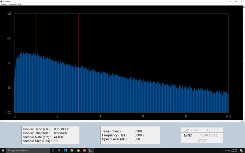
The vertical red markers are at 1,000Hz and 2500Hz. The response is down about 40dB at 10KHz, and only 20-25dB down at 6KHz. For a steeper roll-off, you could add more poles, or employ an active filter. You can read how I used 5532 op-amps to make some really nice, and effective filters for my Sproutie MKII regen. However, it is well worth considering the benefits of a wide response, namely, the ability to listen to a fairly wide swath of the band at one time. This is great for general listening on a speaker when you are doing other things in the shack. With CW, even if there are several signals in the passband, you can train your ear to hone in on one of them and ignore the others. If not keen on this idea, I’m thinking that a SCAF filter connected to the speaker jack, would provide a good way to achieve extra selectivity when needed. However, there are advantages to the wider bandwidth of a relatively unfiltered direct conversion receiver. The simple RC filter in this circuit cuts out the high pitch hiss that can make listening to these receivers so fatiguing. When tuned to 7030KHz, I can effectively hear anything that comes on the air between about 7022 and 7038KHz – a 16KHz bandwidth. It’s my own aural panoramic adapter! The higher pitched signals will be lower in amplitude, thanks to the filter, but you’ll know they are there, so you can retune if you want to listen to them. Nevertheless, if I were building this again, I think I’d use .01µF caps for C1, C2, and C3, and add an extra pole, with an extra 4.7K resistor and .01µFcapacitor.
Once you’ve built the low pass filter, touching the input should give you much the same sound from the speaker as when you touched the input of the 2nd preamp, but with a lot of the high end hiss muted. Onwards and upwards! Build the first preamp, and you’ll be rewarded with the same slightly muted sound, but more of it (i.e. louder). Congratulations – you have completed a very important part of this receiver, and now have an audio amp with lots of gain, and relatively low noise. With the AF gain pot turned to full, you will hear a fair amount of noise, but remember that this is an amplifier with a lot of gain. The best reminder of this will be when the receiver is completed. I absolutely wouldn’t recommend turning the volume pot up to full with no antenna connected (especially in the lower part of the HF spectrum), then connecting an antenna, as the band noise alone will blow your socks off. To reiterate, this amplifier has a lot of gain!
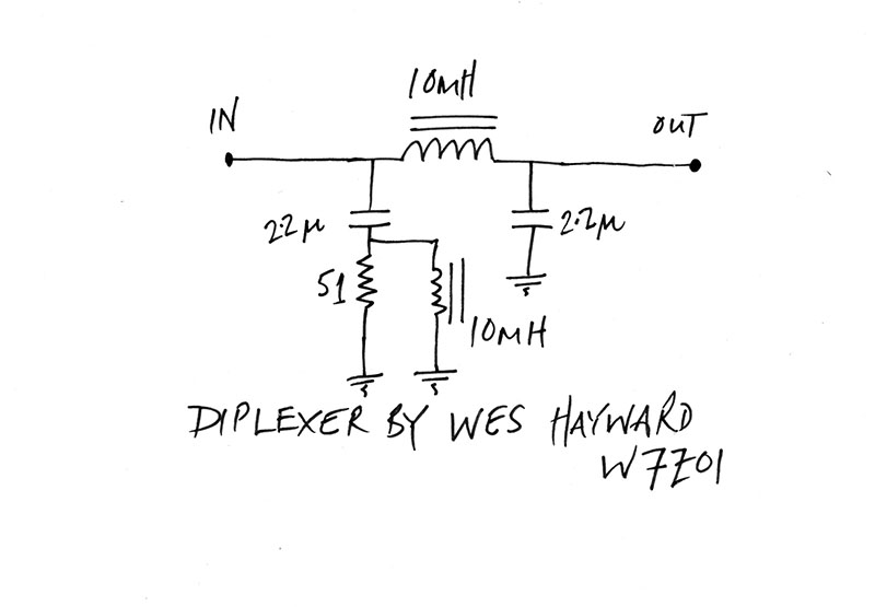
In Todd’s original article, which I will say again, I do recommend getting hold of by downloading the archive of his original site, he details several different diplexers, from which you can take your choice. Some are his design, while others are those of Wes W7ZOI. I chose the (A) diplexer, which was a design by Wes. It used 2 x 10mH inductors, and a couple of 2.2µF capacitors –
A word here about capacitors. Audio folk aren’t keen on the use of electrolytics for coupling in audio circuits, and many prefer the use of poly-something capacitors, which have a much more linear audio response. By poly-something (a prof Vasily Ivanenko coined term), I mean polyester, polycarbonate, polypropylene, or similar. Mylar capacitors are polyester, so are applicable here. For the type of audio standards most of us hams have, you are probably fine using electrolytics for audio coupling. However, since I discovered that the polyester film capacitors from Tayda Electronics are very affordable, I use them for all audio coupling applications, as well as in audio filters.
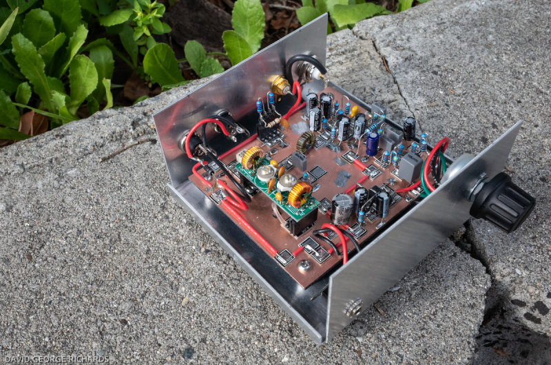
Having built the (A) diplexer, it originally appeared to be working. When walking outside in the street, with the receiver lid off, it was picking up a huge amount of 50c/s hum, which I assumed was coming from the utility wires outside, and induced in the 10mH inductors in the (A) diplexer. This was happening when all stages in front of the diplexer hadn’t yet been built, so that the input of the diplexer wasn’t terminated. I took this as a good sign and continued building. Long story short, when I finished the receiver, it was as dead as a doornail. By a process of elimination (touching inputs and noticing when the noise stopped), I strongly suspected the diplexer. However, it had appeared to be at least passing an audio signal earlier in the build, which gave me pause. It was at this point that I re-read an old blog post from Rob AK6L, and found great succor in the fact that he had experienced problems with the (A) diplexer as well. Rob plumped for the less ideal, but still perfectly functional (C) diplexer, which is what I did too. I know I should have persevered, and figured out why the better diplexer wasn’t working but, at this point, I just wanted a receiver that worked, and so capitulated. In the picture of the board that follows, you can see the reworked section where I removed the old diplexer that took up more space, and replaced it with the more diminutive (C) diplexer. The red wire that emerges through a hole in the board at the input of the diplexer, is coming from the IF port of the DBM, which is pin 2 –

I don’t lacquer my boards any more. It adds one extra stage to the process of building, that I am keen to bypass. Nowadays, when I get the urge to build, I don’t want to add too many extra steps that might diminish my ability to stick with a project to the end. It’s the same reason why I no longer build enclosures from PCB material, when the LMB Heeger 143 fits my needs perfectly. As it happens, I only scrubbed the above board with an old Scotch-Brite pad. I had forgotten that I had steel wool pads in the house. Had I used a steel wool pad, the board would have been a lot brighter. Oh well. It is still perfectly functional. Both the LM386 and ADE-1 mixer, are mounted on Rex’s 8-pin DIP PADS, by the way. In retrospect, I do wish I had scrubbed the board with a steel wool scrubbie, so that it would be brighter and prettier. Next time.
Once the DBM is installed, you can inject your local oscillator signal and start listening, to ensure that it works. The BPF will “clean up” the signal, but you’ll still hear plenty without it. You’ll just hear signals that are on other frequencies too, thanks to the harmonics of the LO mixing with RF from the antenna. If, like me, you’re using an Si5351 or similar device for the LO, you may experience mixer products from LO spurii too, as well as LO harmonics.
Once you’ve verified that your receiver works, you definitely want a bandpass filter on the antenna input, so you can be reasonably sure you are listening to signals within the passband of that filter, and little else. It is educational, and quite surprising, to hear how much cleaner the band sounds with a bandpass filter! Being in the SF Bay Area, there are quite a few AM stations close by, both strong and medium-powered. Without a bandpass filter, there are many specific frequencies throughout the HF spectrum on this receiver, where I can hear some of these stations. Bandpass filtering removes these unwanted mixer products very effectively. If you are constructing this receiver for a single band, you can build the BPF directly onto the main board – no need for plug-in filters. So far, I have built just one BPF, for the 40M band. A NanoVNA proved very useful for tuning it for optimum results. I may build BPF’s for other bands. However, because I really want access to all of the HF spectrum, it occurred to me that would take a lot of plug-in filters! I am now looking into building a passive, tunable pre-selector. Stay tuned* for details.
(* preferably with a high-Q tank circuit 😀 )

The receiver is housed in what has become a firm favorite, the LMB Heeger 143 plain aluminum case. Measuring 4″ x 4″ x 2″ high, it is stout and, with little vinyl bumpers on the bottom, stackable. Perfect for building up a little QRP and SWL station. I get them from eBay for $15.39 including shipping (+ tax). If I want one with a perforated cover, such as the enclosure used for the Si5351 VFO, I order those direct from the factory, as no-one else seems to stock them. You pay a bit more when ordering direct from LMB Heeger. They also have these enclosures in painted smooth grey finish, as well as a black non-smooth finish (almost like a crackle, I seem to remember). I am curious to know what the latter looks like, but the plain aluminum is a “classic homebrew” look, and leaves lots of options open for later finishing – if that ever happens –
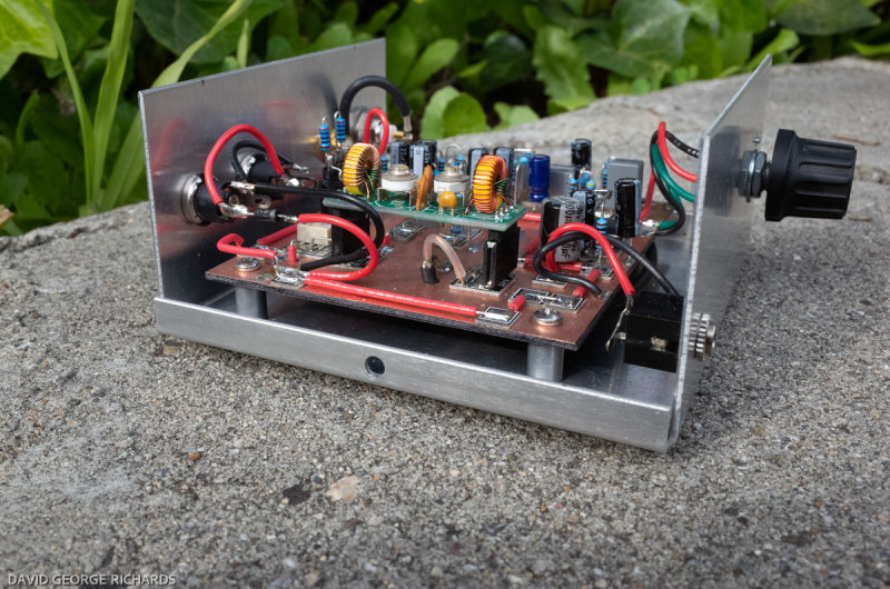
The coax bringing the RF from the antenna socket to the input of the bandpass filter, is routed underneath the board. It comes up from below, through a hole drilled in the board, as can be seen in this next shot –
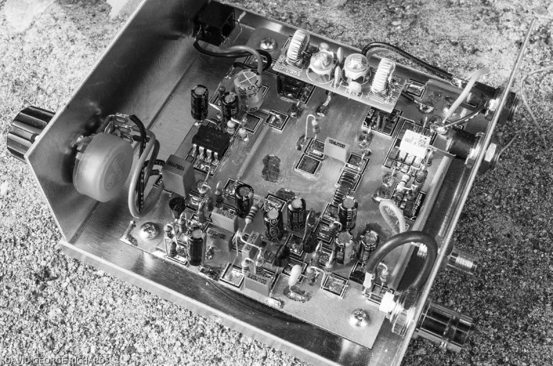
I must admit that I am bugged about two things. Firstly, that I cannot find a free WordPress theme for this blog that has clean, uncluttered lines, and that also allows for larger images. Schematics especially, need more space in order to be clear, which is why I had to resort to breaking this one up. The second thing that is bugging me concerns this project specifically, and that is the fact that I didn’t scrub the board with a steel wool pad before building on it. This build is perfectly functional, and I am happy with it’s stability, and apparent reliability. I just wish the insides showed a little better. I need to get over this.

Perhaps it looks better in black and white………..
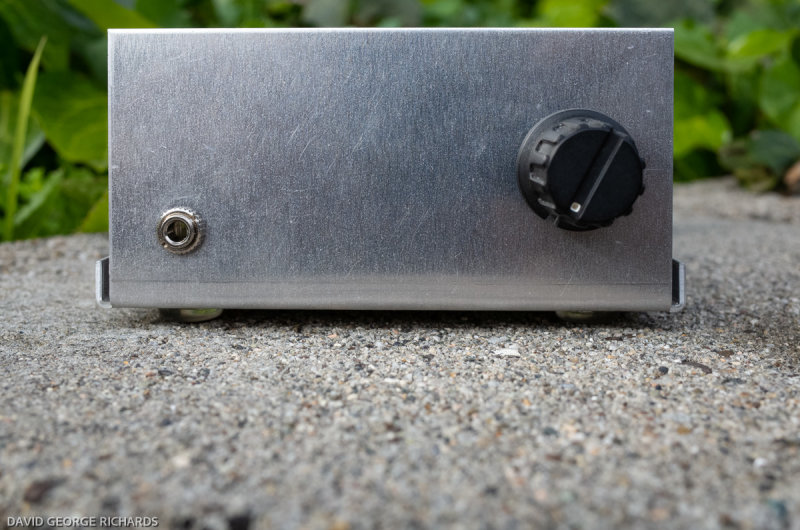
The front panel is simple, and very plain. Speaker/earphone jack on the left. AF gain control on the right. One of these days, I’ll get a Dymo or Brother label-maker, to complete the classic homebrew look. It will also help anyone who might inherit my homebrew efforts in the future, to know what they have, and which knob does what! –
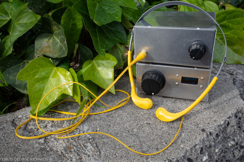
On the rear panel are, from left to right, the antenna jack (BNC), the VFO input jack (SMA), and two 12V DC connectors. They are connected in parallel, so that one power cable can supply the circuitry in this enclosure, and a short power cable can run from the other connector down to the VFO, mounted directly underneath –

A shot from the rear, showing the interconnections between the Si5351 “VFO” on the bottom, and the receiver on the top. Having the mainframe up top makes it easier to pop off the cover to change bandpass filters –

Each case is 4″ x 4″ x 2″ high, so the stack is 4″ x 4″ by a little over 4″ high. The Altoids tin and playing cards are for scale –

This is a practical and useful little receiver. Many receivers of this type just drive headphones. For me, having a receiver that can easily drive a speaker makes a huge difference in the amount of time spent listening. Since building it a couple of weeks ago, I have listened every day, for virtually all the time I have been at home. I couldn’t have done that on headphones. Thank you Todd Gale!

Fascinating reading as always, your work is so encouraging to see, it inspires me to continue in radio electronics, for the past forty or so years I have also built many a project using the man Hatton style of construction, the price is of the pads has forced me into another direction of build style, I’ve decided to go down the route of making my own cnc lazer pcb cutter, using old dvd rom drives, simple effective and smart in appearance. The information I have received from you i will read and have a look and see what parts I have and will need to get, and get stuck in, thank you for sharing 😊 I will keep you posted with progress. Best regards.
That’s an interesting approach Peter. I’ll be interested to see pictures. It’s good to know you find things of interest and encouragement in my posts. We all learn from each other. Sometimes, it’s just fun to see what other people are doing. Best of luck with the CNC laser PCB cutter!
73 for now,
Dave
AA7EE
Another beautiful build, Dave! Glad you’re enjoying the Popcorn Mainframe, I should dig mine out and put it into an enclosure one of these days. I really like the way the Si5531 and the receiver enclosures look all stacked up – clever work on the parallel DC jacks too. Looks like they’re part of a whole family of devices, all meant to connect together. Brilliant!
The attenuation pad on the header strip is handy, I’ll have to try that method in the future.
I wanted to also point out that Professor Ivanenko’s marvelous original QRP site was also regularly crawled by the Internet Archive, and is easily accessible via their Wayback Machine. I selected a random scan in 2014, as that’s the year in which the original was archived and the new site created, but I’m not sure I grabbed the absolute last changes he ever made there. Some digging around in the 2014 archives is probably warranted to find the last crawl before the sunset of the original site. In any case, you can find it here – https://web.archive.org/web/20140316035048/http://qrp.pops.net/ – completely browseable just as though you were at the original site, as far as I can tell.
Keep the projects coming, I always enjoy reading these write-ups.
73 de Rob AK6L
It didn’t occur to me to check the Wayback Machine for Todd’s old site. Great idea! As useful as it is to have the PDF, it’s even better to see the old site in all it’s glory.
Interesting that we both had problems with the (A) diplexer, though I don’t think it has anything to do with the design. It was probably a case of operator error in both of our cases! Like you, I just wanted a receiver that worked, so plumped for the simpler circuit.
You and Jason were the inspirations to build this receiver (and Todd, of course). It was Jason who gave me the inductors which were crying out to be incorporated into a diplexer. They became part of the ill-fated (A) diplexer, but if it weren’t for them, and you, the receiver might not have been built at all.
73 for now,
Dave
AA7EE
Dave, your posts are delightful, equal parts autobiography, instruction and inspiration. I too built a DC receiver, mine around the late 1970s, with one of those rare new-fangled things, a 4-legged dual gate MOSFET, a 3N211 in an insect-like case. I was surprised and thrilled with how well it worked on 40m, my first experience of a wide bandwith HF receiver. I could hear half a dozen CW signals at once, all spaced around the audio spectrum, and, incredibly, my wetware had the ability to zoom in on just one, with adequate concentration. I later built a TenTec 1060 DC receiver kit, and this project I still have. In fact I turned it on recently.
I too enjoy running a homebrew receiver in the background, to monitor the liveliness of a band as day and night alternate, it is a kind of mood-setting aural clock. I always use an audio power amp IC that is more than capable of driving a speaker for this reason.
Keep building, writing about and photographing, and enjoying radio!
73 Paul VK3HN.
Thanks Paul. I’ve been frustrated with WordPress recently, as they limit the size of my photos and apply extra compression to them. I don’t like the way they turn out, but it is too arduous to move the blog somewhere else. I am not prepared to put that amount of work into it, so will keep on putting up with the status quo.
I am hoping to spend some considerable time motorhome camping in the American West over the next couple of years, and some of this homebuilt gear will be coming with me!
Yes, a wide receiver with no AGC gives you a clearer picture of general band conditions. It’s a bit like an old sports car. The ride is harder work, due to the lack of suspension but, at the same time, feeling every bump in the road puts you more in touch with it!
73 for now,
Dave
AA7EE
Well, when the US West is accessible to you, why not see it?
There’s a grand Australian tradition of retiring, then touring up the east coast and into the centre to escape the southern winter. I hope to do some of that one day. A roaming friend was in central Australia last winter and the Covid border closures stopped him from returning home. He didn’t care, he subsequently drove to Far North Queensland.
Keep blogging from the road, when the time comes.
73 Paul VK3HN.
Hello Dave. Your work is excellent. I am a beginner radio amateur. I live in the city of Barnaul, Altai Territory. Here in siberia frosts reach -38, but your article warms up and gives pleasure from what you see and read.
73 Konstantin RA9YRU.
Konstatin –
I am happy to know that you are reading my blog in Siberia – and that you are enjoying it. Thank you so much for letting me know!
73 de Dave AA7EE
Dave!
It’s great to see you posting again! I hope you and your kitties are all well.
No problems here in Las Vegas. My wife and I are fine. I have been busy with flight instructing, church, and music. In 2017 the FAA told me I had too many birthdays to continue flying for Southwest Airlines, so now I am retired from that and have more time to enjoy other activities.
I did home-brew a 30m DC receiver, but it’s rather deaf. So I was elated to see your latest project is a DC receiver, and a simple one too. I will be scrounging in my junk box to see if I have all the parts. Thank you for all the details too!
I sympathize about tossing old gear, especially your home-brew DC rig. I would chalk it up to temporary insanity, in your defense, HI HI! I have done a similar regrettable tossing, when I was moving and tossed three or four AM tube radios made in the 40’s and 50’s. Sigh…. What was I thinking???
Oh well.
I relocated to my present QTH 5 years ago. There’s just enough room for a full-size 80m delta loop antenna. It works great, and tunes up on all but top band. My main rig is still the old reliable Flex 3000, which is 10 years old now.
So take care my friend. It’s great to have you back.
Rob Pursell N7REP/ ex KD7KAR
>
Rob –
I don’t know why I didn’t see your comment at the time you made it. I’m sorry about that but, in my defense, I have been severely tailing off in my building and blogging activity in recent years. This post was something of a last hurrah – a final burst of homebrewing of energy. I have also been quite lax at keeping up with blog comments.
Roger on the new QTH and retirement from the main job. You are such a well-rounded and active person, I have no doubt you are filling your days with engaging pursuits. It’s a good thing to keep busy and engaged, though retirement also gives you the opportunity to take time off whenever you want, which is a great luxury!
I’ve been having fun with a campervan for the last couple of years. I don’t think it’s going to be quite the long-term pursuit I originally thought it might turn into. However, working on it and traveling in it has been fun. I may take another trip or two before passing it along to a proud new owner. You never know if something is for you if you don’t try it.
Back in May, I had a right knee replacement. Recovery is going well, and I hope to be able to ride my bicycle around town once again in the next month or so. It is good to be gradually getting back to regular activities. I don’t play any sports, but have severely missed being able to go on hikes and long strolls.
Anyway, that’s about it. I am looking around for a new interest to learn. The author Malcolm Gladwell says that, in order to become superbly accomplished at something, you need to put in about 10,000 hours of practice, which equates to 3 or 4 hours a day for 10 years. I’d like to become good at something new, so am thinking that perhaps I can get there in 5 years. I’ll take good over great!
73 for now OM, and good to hear from you.
Dave
AA7EE
Nice to hear from you, Dave. I have been very negligent in keeping up with my blog,
The Commo Bunker. Need to get back there and pontificate some more.
Gonna take a hard look at this DC mainframe idea. Looks like a great idea. George Burt, GM3OXX did a lot of modular building and his gear was immaculate!! Unfortunately, he passed about 3 years ago. Lost George Dobbs, G3RJV, last year. The QRP Old Guard is slowly disappearing. I turn 75 tomorrow. Been at this ham radio hobby for 58 yrs. Got my license in 1963 and haven’t looked back.
Stay safe, Brother.
Vy 73
Rich K7SZ
QRP ARCI, G-QRP, NoGA, SEDXC, WWDXC, PARG, M-QRP-C, SKCC, MRCG, Barrow ARC & Colonel, Wyoming Valley QRP Commandos.
Author: ARRL’s Low Power Communications, all 4 editions.
QST QRP Editor 2000-2004
________________________________
Rich –
It is always good to hear from you. Yes, a lot of our QRP and homebrew heroes are moving to the great shack in the sky. I’m a little younger than you, at 57, and am hard pressed to remember a time when gentlemen like the Georges (Burt and Dobbs) were not a part of my radio consciousness. Luckily, a lot of their work lives on, thank goodness, in the form of their writings. I’ll be reading their work in back issues of SPRAT and elsewhere, for the rest of my days.
Hope you’re staying happy and healthy. Strange times we’re living in, for sure.
73 for now OM,
Dave
AA7EE
dit dit
Hi Dave de KD1S. Great write up. And I know what MOSFET stands for Metal Oxide Semiconductor Field Effect Transistor.
Hi Dave,
I’ve been testing building circuits on various development boards and decided that Rex’s products are the way to go. I bought a sample kit and have only one question. What do you use to secure the pads, squares, etc. to the scrubbed copper covered boards?
Thanks and 73s Jack W6VMJ in Fort Collins, CO
Hello Jack!
I use superglue in the gel form to attach the pads to the board. The non-gel type is too runny, and has a tendency to end up all over the place. Once I’ve decided where the pad will be attached, I scrape the area on the board (under where the pad will go) with a small jewelers screwdriver, to roughen it up a bit. I also scrape the underside of the pad with a sharp blade (box cutter, Exacto etc). Then, I put one small drop of gel on the board, and place the pad on the board with pliers. The next part needs to happen quickly. I push down on the pad with a jeweler’s screwdriver (or small pliers), taking care to ensure that it is square. Once you have pushed down on the pad, the glue begins to set. From that point you have a few seconds to readjust the positioning. I usually reposition with a small pair of pliers (you can reposition as well as push down on the pad with the pliers).
If the pad isn’t square, and it becomes glued to the board before you have a chance to reposition it, you can push a sharp box cutter blade (Stanley knife blade or similar) under the pad, and it should pop off. Sometimes, applying rotational force with pliers will also cause the pad to pop off. You’ll need to scrape off the old glue from both board and pad, before trying again.
I hope that helps, and best of luck. Rex’s pads have really worked well for me. I hope they work for you too.
73 OM,
de AA7EE.
If you don’t have a copy, you should beg, borrow or steal a copy of Experimental Methods in RF Design — there’s a great section on DC receivers by Rick Campbell KK7D, which may cause you to go down several very interesting experimental rabbit-holes to test new things out.
I know it did that for me!
73, and hope to work you some time
Jim KK0U
Hi Jim – I have a copy of EMRFD, and have read Rick’s work on DC receivers. Great stuff!
73,
Dave
AA7EE
Hi Dave from Croatia…
BIG thanks for fantastic idea od DC Receiver…73 de Mikele 9a3xz
That’s fantastic Mikele. Thanks for posting your video!
73
Dave
AA7EE
Really enjoyed reading your post, I’ve just re-started ham radio and am experimenting with a uSDR rig using the Tayloe mixer which can be a bit harmonic with the volume up, and is picking up those local AM stations. It’s also interesting reading how fixated you got with that receiver project because the same happens to me… I wonder what it is that addicts us so much to radio techniques?!
73, Rob, GW8RDI
I think the fixation is necessary, so that we see some of these projects through to the end Bob. When I was building a project, a large part of my life was given over to it, for however long it took to complete. This could be why I am not married!
73 for now,
Dave
AA7EE (ex G4IFA)
Dave, one thing about using the W7ZOI diplexer above, is that there is no DC block between the ADE-1 and point A in the first amplifier in your drawing. There’s a bit of emitter bias at point A that would unbalance the diode ring at pin 2 of the ADE-1. That might have been the trouble you experienced.
I love your workmanship and attention to detail. It’s fantastic.
Cheers,
Kenn
KA5KXW
Kenn – thank you for that observation. It never occurred to me to think about the direct DC path that exists through Wes’ diplexer. I bet that was the problem.
73 for now,
Dave
AA7EE