

This was a fun little project – and it gave me an idea for a future one. Sometimes, I find that the more complex undertakings, which require more planning, can get to the point that they “take me over” somewhat. At that point, for me, some of the fun starts getting squeezed out and that, of course, absolutely cannot be allowed to happen. This is the time when simple and fun projects save the day.
QRPp beacons have been a “thing” of mine for a while now, ever since I put the Sproutie SPT HiFER Beacon on the air, sending it’s 12 wpm SPT ID out continuously on 13558KHz, with a mighty 4.6mW to a much shortened loaded dipole. That signal was spotted by a few people, including one spot 900 miles away. SPT is not on the air now, but it’s sitting here in the shack, “just in case”. It was a legal, though unlicensed, beacon, courtesy of the FCC Part 15 regulations. The idea that a signal which is so miniscule that it doesn’t even require a license to be radiated, can be spotted so far away, is quite wonderful to me. Others have had their HiFER beacons spotted from one coast to another – and that’s with regular Morse code speeds. Imagine what you could do with QRSS on that band – which some experimenters do.
After assembling a QRP Labs U3S for my ham friend, my mind turned back to some of my personal interests, and mental stash of “things to be built”. In the world of experimental HF beacons, as well as the legal HiFERs, there are also a good number of signals dotted throughout the HF spectrum that are not licensed (i.e. pirate beacons). I remember, shortly after moving from Los Angeles to San Francisco, I was living in a ground-floor apartment just 3 blocks from the Pacific Ocean. It was wonderful falling asleep at night to the sound of fog horns. Just as evocative, and exciting, was hearing, for the first time, one of these low-powered pirate beacons on my FT817 hooked up to a Buddipole inside my apartment. It was one of a cluster of beacons around 4096KHz, and situated in one of the southern deserts – Mojave, I believe. None of the beacons in that cluster were putting out more than around a watt, and they were out in the desert, sending their brave little signals across hundreds of miles to my receiver in the SF Bay Area. Magical! These beacons have all sorts of different sounds, varying from chirping, bleeping and whooping, to actual Morse ID’s. A few have temperature sensors, and send the current temperature. I think one even has a windspeed indicator. It may not necessarily be particularly useful information, but it adds a bit of interest to the predictability of a simple ID sent over and over again.
That’s what got me to thinking of building a little temperature beacon and, after some browsing and searching, I came across a simple and effective design by Sholto K7TMG. You can read his very informative write-up on it here –
It’s a simple one-transistor Colpitts oscillator with the positive supply line keyed by an ATTiny13 micro-controller. The genius (as with so many things these days) is in the code that Sholto wrote. It converts the analog voltage from an LM335 temperature sensor to Morse code and announces it, about once a minute, in both Centigrade and Fahrenheit. When the article was first published, he was offering pre-programmed ATTiny13’s for $5. He has since discontinued that offer but instead, has made both the source code and a hex file available on his site. The links are in the article above. I had trouble compiling his source code which, I’m fairly sure, was due to user error at my end, so I simply burned the hex file to an ATTiny 13V-10PU using my Etherkit Etheprog ISP and KC9ON Programming Adpater from Third Planet Solar. Any similar AVR in-system programmer would work fine, such as the Tiny AVR Programmer from Sparkfun, or you could use your Arduino to program it. I’ll leave it to you to figure that out. There’s plenty of good info out there in internet-land.
Before I start raving about this little circuit, I want to show you my version, which is identical to Sholto’s, except with the addition of two resistors at each end of the trimpot to make calibration of the thermometer a little easier, and a different value of the molded choke in the oscillator collector circuit (his was operating at 4MHz). I used a different value of trimpot too. I did try to contact him, but didn’t hear back, so I hope he won’t mind me showing my slightly altered version of the schematic here. (Edit – I have since heard from him and am still crossing my fingers that he won’t mind my going ahead and doing this).

One thing that I particularly like about this circuit is that the oscillator is keyed, meaning that when it’s not actually sending, it’s not drawing current – or so I thought. It also means that when you’re close to the transmitter, there is no backwave to hear. On keydown, the oscillator only draws about 3 mA. Seeing that it only sends the temperature once a minute, I initially thought this meant that the average current draw of the whole circuit (considering that the current consumption of the ATtiny13 is well under 1mA) would be something around 1mA, making battery operation for long periods quite feasible. However, I was forgetting that the quiescent current of the voltage regulator chip is around 3 or 4mA, making the average current consumption of the entire circuit somewhere in the region of between 4 and 5mA. Of course, this is still not a lot, but it does mean that my original plan to power it solely from a 9V battery was now on shaky ground.* With an approximate capacity of ~500mAH the average 9V battery would only last a few days. Zener diodes need a few mA flowing through them to get proper voltage regulation, so that wasn’t a practical alternative to get the current draw down. It would be possible to run the circuit from a lipoly battery with no regulator in-circuit, but the LM335 temperature sensor relies on a stable reference voltage if the calibration is to remain accurate. At this point, I decided to stick with the circuit as-is, and accept the current consumption. 5mA is definitely not high – it’s just that when your circuit only draws about 1mA on average, the 4mA required to regulate the voltage for it seems a bit out of proportion – and from the perspective of a QRPer, one thing I like about these micro-powered transmitters is the small amount of power they need to operate.
* Dan M0UWT suggested that I look into a more modern voltage regulator, with very low quiescent current, such as the LP2950 series. These have quiescent currents of less than 100uA, making them ideal for an application like this. Thank you Dan. I’m not sure why it didn’t occur to me that less power hungry devices would be available now. I think it was the the fact that I already have a fairly good stock of 78L series devices in my parts drawers that was blinding my thinking!
*Update (Nov 16th 2020) – I just swapped out the 78L05 regulator for an LP2950. Average current draw with the 78L05, taking into account both key up and key down periods, was ~5.9mA. With the LP2950, it is ~2.5mA, a step in the right direction.
**Second update (Nov 17th 2020) – I noticed that, with the LDO (low dropout voltage) regulator fitted, the temperature readings were varying wildly. One minute, it would transmit 66°F then, a minute later, it would decide the temperature was 77°F, from which point it would then transmit 69°F! I don’t know why it was doing this, but on putting a 78L05 back in, the operation went back to normal, with transmitted temperature changes occurring much more gradually.
To get started, I breadboarded the circuit. RF circuitry doesn’t always do too well on breadboards, and the frequency stability of this one did suffer a bit. Also not helping was the fact that this particular breadboard had no ground plane underneath it. My other breadboards, which all came from Radio Shack, come with aluminum sheets that can be placed underneath, and connected to ground. This mini breadboard was a test purchase from Adafruit. The lack of a groundplane sheet, along with the fact that it seems to have a slightly higher insertion force than my RS ones, will mean that going forward, it will be my least favored breadboard. Sorry for the unattractive desk lighting, but it was late at night, so the opportunity to photograph outside wasn’t there –

The jumper wires tend to obscure the components, but in the following shot, you may be able to see the ATtiny13 in the middle of the board at the left-hand side, and the 13.56MHz crystal just above and to the right of it. At this point, I was experimenting with fixed capacitors in the oscillator tank circuit instead of a trimcap, so you can see an NPO ceramic standing up proudly to the right of the crystal. The free black lead is a small antenna connected to the emitter lead of the transistor –

With this arrangement, I found that the adjustment on the 10K calibration pot was very critical. To help combat this, I measured the approximate resistance of the pot from one end to wiper when calibrated, and used this to estimate the range of adjustment I wanted to focus on. My final built version included an extra fixed resistor at each end of the potentiometer track, so that the entire range of trimpot adjustment was focused within a narrower range of voltage values. If you want, you could start with the values of fixed resistor that I used, only adjusting if necessary.
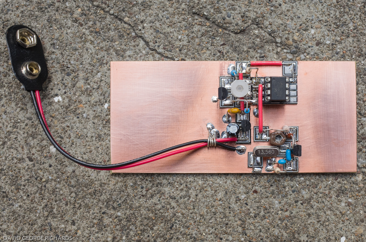
There’s not too much to the construction. You can see the LM335 temperature sensor standing tall on the board. I didn’t clip it’s leads, as I didn’t yet know where it would finally be positioned. The ATtiny13 is not fully inserted into it’s socket either, just in case I decided to modify the code (which at this point, doesn’t look likely). You can see that the left side of the crystal is connected to ground via a pad (one of Rex’s MeSQUARES). I did this instead of soldering it directly to the ground plane in case I later wanted to use a series trimcap to adjust the operating frequency. As pictured, it came up on 13557.3 with no extra series or parallel capacitance, which works fine for me. In this band, most beacon operators avoid the ±1 or 2 KHz around the center frequency of 13560KHz, as this is where the greatest density of the industrial and scientific non-hobbyist operation occurs (RFID devices, machines used for the dielectric heating and drying of wood, etc). The entire band is from 13553 – 13567KHz, so this still leaves a fair bit of room for narrowband modes such as CW. Lots of room for QRPp beacons! –


A shot from directly above. Unlike with most of my previous Manhattan projects, I didn’t lacquer the board this time. I’m curious to see how it fares over time.
Calibration is a simple matter of using a thermometer (digital or otherwise) of known reasonable accuracy, and adjusting the trimpot in this circuit until the readings match. I don’t have a thermometer, but I do have the thermocouple attachment that came with my DMM, and used that. I don’t know how accurate it is, but the readings seem pretty close. Quite honestly, I’m not really that interested in knowing the precise temperature anyway – it’s just a fun way to include some variable data in a beacon transmission.
I had originally intended to mount this circuit in a weatherproof enclosure out on my balcony, so that learning the outside temperature would be just involve tuning a SW receiver to the right frequency. However, I decided to keep it as a circuit on a board, and just use it casually around the shack. It gave me ideas for my next project though – another HiFER beacon. Stay tuned for the details!
Here it is in action, with a special appearance at the end by Boris, my neighbor’s cat. Apologies for the slightly crummy video quality. Video is not my forté –

Dave, as always another great build, and the video is just fine. Thanks!
Thanks Dave!
A fun project Dave. I agree that you need to keep builds small, about a day’s work. A rig then becomes a collection of module build efforts. There’s an analogy to sprints in agile software development methodology in there somewhere. A sprint of soldering and debugging gets a module working. On other matters, I like the way you drew the LM335, when I googled it, it turns out the three-legged diode symbol is used generally. On the 78L05 quiesent current, I am not a surface mount aficionado but I’ll bet there’s a tiny rice grain part that performs better than the venerable crusty old 78L series regulators. Most things modern are 3v3 now but the 5v legacy should deliver something. Enjoyed your post as always! WSPR for AA7EE next? –Paul VK3HN.
I had seen that 3 legged diode symbol before Paul, but had to remind myself how to draw it, as it’s one I use very rarely. I’d use software to draw schematics, but it’s fun drawing them freehand on paper, even if they do come out a bit “wonky”! I already have an order in for some LP2950 low drop-out and low quiescent current (110uA) 5V regulators, at the suggestion of M0UWT. I’ve built kits with these parts before but, for some reason, have always stuck to the 78 and 78L regulators for my scratch-built projects. I’m a slow learner. Not sure why that is!
WSPRing happens here from time to time. As with many things to do with radio, I enjoy setting these things up and getting them going, but the interest wanes a little and my mind moves to the next project, once something is working. It can be something of a curse!
I happened across this project on Hackaday and was immediately attracted by the Manhattan style construction. I’ve got a breadboarded project of my own that I’m about to rebuild using Manhattan style and have been looking for examples. Yours has given me some ideas and techniques that will be very useful in my own implementation, so thank you for posting this, and particularly for the photos from multiple angles.
Whoops, sorry. I meant Dangerous Prototypes, not Hackaday.
John – glad that the photos helped. My first attempts at Manhattan construction were a bit shaky, but some practice helped a lot. I’ve built quite a few things using this method of construction. If you want to see more pictures, a stroll back through the last few years in this blog should yield some more photos. Best of luck with your rebuild!
Dave
AA7EE
I’ve been planning on doing this with your Sproutie beacon. Removing some of the jumpers for WPM and adding a temp/humidity sensor. I’ve got all the parts, just havn’t built it yet.
Let me know if you ever do. Dayne. I’ll be interested to know how it works out – and to learn details too!
Dave
AA7EE
Nevermind, looking further on your page I discovered the “MeSquares” and “MePads” from qrpme. Good stuff, those are exactly what I was hoping that someone had already made for me!
Ooops – typed this before noticing that you had found out what they are. Will post anyway!
John – they are MeSQUARES and MePADS from QRPMe –
http://qrpme.com/?p=product&id=MES
http://qrpme.com/?p=product&id=MEP
Rex also makes smaller pads, which are useful for tight spaces –
http://qrpme.com/?p=product&id=STX
There’s also this sample pack –
http://qrpme.com/?p=product&id=SAM
All this reminds me that it’s nearly time for me to order some more!
Where is the sound coming from? Is it coming from the tiny micro controller?
No Tarin – it’s the off-air signal, coming from an Elecraft K2, tuned to the frequency.
Cheers!
Dave
AA7EE
Someone should sell this as a kit.
An idea for QuirkyQRPHamRadios, perhaps James?
We have to build and deploy some with Geiger counters…
Funny you should say that Roger. I was just looking at a simple circuit for a Geiger counter from a book that I had as a kid.
Hello AA7EE
Good time
Dear David, I need your guidance and advice.
Please, if you can send a message to my email or put your email so that I can send you a message.
Thank you.
My email is good on QRZ erfan. Alternatively, feel free to put your question here. I’ll do my best to help, if it’s a fairly straightforward question and answer.
Thanks for your attention David
Let me give you an introduction.
As we know, the basis of the operation of Morse transmitters was that they sent an electrical discharge pulse and the receiver received these pulses. Later, the same method was done wirelessly, and most ships received and sent pulses using this method until a few decades ago. Electric discharges sent and received information in the form of Morse code.
I’m trying to build a long range electrical discharge pulse receiver that can receive wirelessly.
Today’s receivers use advanced filters to purify the reception due to the great advances in science, but I prefer the old ones because in this particular case, the old Morse code reception circuits (electrical discharge pulses) could have small discharges and to identify the small ones that had very little power.
Can you give me a guide or introduce a circuit in this matter?
Thank
Erfan –
Spark transmission fell out of favor about 100 years ago, after World War 1, when vacuum tube transmitters were developed. The first receivers employed coherers. I don’t know much about this era of radio, but I think that the technology developed to the point that TRF receivers were used to receive spark transmissions. Before TRF receivers used vacuum tubes, but after coherers, were receivers that, as far as I can tell, were a type of passive crystal set. The receiver on the Titanic used a magnetic detector that radio operators called a “Maggie”.
Click to access Titanic_wireless.pdf
I’m sorry, but I don’t know much about radio transmitters and receivers of this period!
Thank you very much for your reply.
Dear David, the truth is that there are findings that I am ashamed to recount, lest I be ridiculed. But I will say briefly.
Valuable metals such as gold and silver, when they have been buried under the soil surface for a long time, for example 40 years, produce a trace of themselves. This trace is transferred to the surface of the soil. I use a modified FM receiver circuit and with Using an internal 8MHz oscillator I can detect this effect.
It has been experimentally proven that this effect is a kind of very, very weak electric discharge around microvolts, which can be identified as AM wave harmonics but in the FM range. I live in Iran. They have discovered the value. Me too.
But this method has limitations. I am trying to be able to reveal this effect from further distances using the same method but by making changes.
I draw your attention to this link.
I use the latest version of this circuit with the changes I have made.
I found your activity beautiful and interesting. Maybe the information in this link can give you interesting ideas or motivations.
Thank you very much for your reply
https://www.longrangelocators.com/forums/showthread.php?t=18933&page=9