

Note – lots of photos, so please allow time for them to load!
In a previous offering, I posted a few photos and a brief description of a QCX 5W CW transceiver from QRP Labs that I recently assembled for Fred, a ham friend. It was fun, because I got to assemble and experience first-hand, a kit that I probably wouldn’t have otherwise. It’s quite remarkable that a QRP transceiver with such features and performance can be purchased for $49. In a recent interview that Hans did with Martin Butler of the ICQ Podcast, he admitted that he was aware he could be asking more money for these kits, but said that he wanted to get them into as many hands as possible. We’re lucky to have such a gifted and enthusiastic designer in our midst. On top of that, he’s a particularly pleasant fellow too! I recommend watching it if you haven’t had the pleasure of seeing Hans speak before. It’s heart-warming not to have to separate the person from their art – and that’s one of the very agreeable aspects of this niche in our hobby. Hams who are into rolling their own – whether from scratch or kits, seem to exemplify the gentleman ham spirit that, for me, has always been a cornerstone of our hobby. From the local ham who gifted me my first shortwave receiver, a British military R107 receiver that set the standard for the term “boat anchor”, to the kindly older gentleman who gave me my first transceiver – a 2 meter FM rig he had built himself, with a tunable LC VFO, to the fellow who filled up my parents’ porch with vintage radio parts while we were out at church, it felt as if there was a community of fellow hams and builders all looking out for me. We’re all quite different in many ways, but we share our interest in building, perhaps even snatching the odd brief QSO along the way, and exchanging an RF “high-five” as Mike Rainey, AA1TJ very eloquently puts it.
Fred was enthused about the QCX, but the first QRP Labs kit we ever talked about was the Ultimate 3S QRSS/WSPR transmitter. It was inevitable that, at some point, we’d get round to discussing it again, this time with a view to assembling one. As with my post on the QCX transceiver, I won’t go into detail on the capabilities and history of the U3S, as you are very possibly already familiar with it. If not, there is plenty of information on the U3S product page at the QRP Labs site.
The basic U3S kit consists of 3 separate kits – the main board, the Si5351 synthesizer board, and the LPF board for the band of operation. Fred also chose the QLG1 GPS receiver board. For just $23, the GPS receiver will regularly calibrate the DDS VFO, automatically determine your Maidenhead locater and insert it into your WSPR transmissions, and provide accurate timing. It makes WSPR operation much more trouble-free. For $23, it’s a bargain. There is also a relay board to switch between multiple LPF’s, for multi-band operation, but we decided to start with just the one band which, in this case, was 17M.
The kits arrived in a small box from Japan. Hans has just announced that distribution will be coming from another part of the word in the future, in order to deal with the high volume of orders. He has hired a full-time person to do this –

The main board was the first one to tackle, and the fact that it didn’t have that many components was quite encouraging!

It didn’t take long to place the components (I am trying to avoid using the word “populate” 🙂 ). The bifilar transformer in the output circuit of the PA can be mounted vertically or horizontally. If, at a later stage, you plan to add the OCXO version of the Si5351 synthesizer board for higher stability, this transformer will need to be mounted horizontally, in order to clear the mini oven enclosure. I decided to go ahead and install it horizontally, just in case we ever add that option. The holes for the transformer leads are placed for vertical orientation of T1. While it is very possible to mount it flat against the board, the placements of the holes for the wires aren’t ideal for holding the toroid in place. I used a small dollop of hot glue to help hold it close to the board. It later came off when I cleaned the board with isopropyl alcohol, and I learned that it hadn’t really been necessary in the first place. The only evidence that this photo was taken before the cleaning, is a small bit of burnt flux along the top edge, along with some light honey-colored flux along the length of the same header strip. You’ll also notice that I installed just one BS170 in the final. I installed a link between A0 and A3, to turn the backlight on, and enable software control of the brightness. This link was later replaced by leads to the left-hand switch on the front panel, to switch the backlight on and off –

Fred’s a very capable and smart guy, but his illness, and the treatment he’s going through, make life pretty tough for him at times. He wanted the U3S to be set up so that it was easy, and fairly foolproof to use. Part of this plan was using just one BS170 in the PA, running from the regular 5V supply, as opposed to more parallel MOSFETS, supplied by a higher voltage. After blowing the finals in Fred’s QCX by accidentally making a single WSPR transmission with no antenna connected, I wanted to set the U3S up so as to make such mishaps unlikely. As part of that whole plan, I didn’t even bias the transistor for maximum output, choosing to adjust it for 200mW output instead. A single BS170 should be capable of surviving transmission indefinitely into any SWR at that power level. On top of that, I think that 200mW is a good power level for WSPR anyway. It’s enough to consistently get spots over long distances, yet well within the QRP ethos of the mode. Personally, I think that 5W is excessive for WSPR!
With the main board complete, I turned my attention to the appealingly diminutive LPF and synthesizer boards, which both come as 2 small bags of parts –

What can you say about the LPF board? It only has 3 toroids and a few capacitors! I will make one small comment though (I hate to call it a criticism. If it is, I think of it as a constructive one). The hole placements for vertical toroids in the QRP Labs kits I have built are not ideal for holding the toroids perfectly vertical. As a comparison, when building my Elecraft K2, I noticed that pulling the toroid wires fairly tight (you don’t want to over-tighten them) caused them to naturally line up vertically, and straight. To someone like me, who is perhaps a little too concerned with neatness, this is a very gratifying feature! I used small blobs of hot glue to help keep them in place –

With the SMD Si5351 chip pre-installed, the synthesizer board isn’t that much more complicated –

The finished synthesizer and LPF boards make such a cute couple. I did end up cleaning the synthesizer and main boards with isopropyl alcohol and an old toothbrush after taking these photos, but left the LPF board as-is –

The main board, with the LPF and synthesizer boards mounted. The view from the other side would simply show the LCD. The neat thing is that, if you have a 5V regulated supply, you could operate QRSS and WQSPR modes with these boards as shown. There are menu and edit buttons already mounted on the board. All you need to do is connect an antenna to the 2 header pins on the left-hand side, just above the button, and a 5V supply to 2 header pins that are barely visibly at the bottom of the board underneath the synthesizer board. You could be on the air with all sorts of fun QRSS and WSPr modes for just $33 + shipping! –

However…….if you did go on the air with just the above combo (and many have), you’ll have to manually calibrate the synthesizer board so that the frequency is accurate. If you plan on using this unit for WSPR, you’ll also need to calibrate the timing oscillator on the main board, so that the internal clock is accurate. Otherwise, the timing will drift off at some point, and you’ll cease getting spots. The GPS board is only another $23 and for that, once you’ve done some initial set-up, the whole thing pretty much runs itself.
So here we go with the GPS board. The RF module comes pre-installed, so it’s really a simple assembly process –

The finished board. You may have noticed that I take most of these photos on the same piece of concrete slab outside, yet the color balance varies a lot. Much of that has to do with the way the lighting changes at different times of day, and with different kinds of weather. If the GPS board is to be used without an enclosure, or mounted in a non-metallic case, the kit comes with a patch antenna that installs on the board. It works quite well, due to the large ground plane on the board. We were using the QRP Labs custom enclosure for this project, and I wanted the GPS board to be mounted in the same case, to make the whole unit as self-contained as possible. This approach necessitated the use of an external GPS antenna, for which I installed an SMA connector on the board. I mounted it a little above the board to ensure that there were no accidental short circuits (such an occurrence had been reported in the builders group on groups.io) –

The enclosure took a little longer to arrive, as it was coming in from China. It arrived via airmail though, so didn’t take the month or two that surface mail can take. Luckily, the timing was perfect, and it turned up in the mailbox a day or two before it was needed. This was the point at which I really started appreciating kits that have all on-board connectors! I wanted it to be possible to disassemble the unit fairly easily for possible future upgrades or repairs, so made all connections to and between the boards with female header blocks. The following photo shows the case with most of the interconnecting wiring, with the exception of the cable between the GPS board and main logic board, and the wiring for the backlight switch. Many builders who mount the GPS board internally, drill an extra hole in the rear panel to accommodate the SMA connector for the external GPS antenna. I wanted to make use of the cutout that had been made for a 9 pin D-sub connector. This connector is intended to be used to connect the GPS board if mounted externally. I fashioned a blanking plate from black PCB material, and drilled a hole for the SMA connector. The back panel is more symmetrical this way, than if I had drilled an extra hole. You also see the 5V regulator bolted to the bottom of the case. I thought long and hard about the exact placement of this part –

Pete ZL2IK, when running his U3S at 5W, encountered some frequency instability. As well as running the full QRP gallon, he was also powering the crystal oven option – all from the same regulator. He details it in this post, as well as describing his solution. He used 3 separate 5V regulators, all bolted to the bottom of the case. One feeds the logic board and OCXO, another supplies the OCXO heater, and the other one is connected to the PA section. He also used ferrite beads over his interconnecting wires, to prevent RF from getting into them. Although I don’t anticipate ever using more than one PA transistor in this unit, I figured it wouldn’t hurt to use ferrite beads. Mine weren’t large enough to go over the wire insulation, so I placed them at the ends of the leads.

A close-up of the inside of the rear panel. If you’re wondering about the reason for the sartorial flamboyance of the RF output coax curled around the BNC connector, instead of proceeding towards it in a straightforward fashion, that was purely because I sometimes like to leave extra length in some of my leads, in case of future mods or repair work. It’s probably over-cautious, and a more directly routed lead would have looked better. That’s a 1uF cap on the regulator input to ground, and a 01.uF one on the output, by the way. There is also a 1N4001 diode wired in series with the positive DC input lead, for reverse polarity protection. Fred is going to use his 13.8V shack power supply, so we’re not bothered about the ~07.V forward voltage drop across the diode –

The 2 sub-mini toggle switches are not the ones that came with the case, although they look very similar. One of the switches that came with the enclosure was particularly stiff in it’s operation, so I substituted 2 from my parts drawers. The reason for replacing both of them was simply so that everything matched –

With the GPS board installed. The right-angle SMA to panel mount SMA was a pre-made lead purchased from an eBay seller. A search for SMA to SMA pigtail”, or “SMA to SMA lead” should get you started. I probably ended up refining my search to something like “right-angle SMA to panel mount SMA” or something very similar. They’re very low-priced if you purchase from overseas (guess what country I’m talking about), but I wanted this one fairly quickly, so opted to pay a few more dollars to an in-state seller –

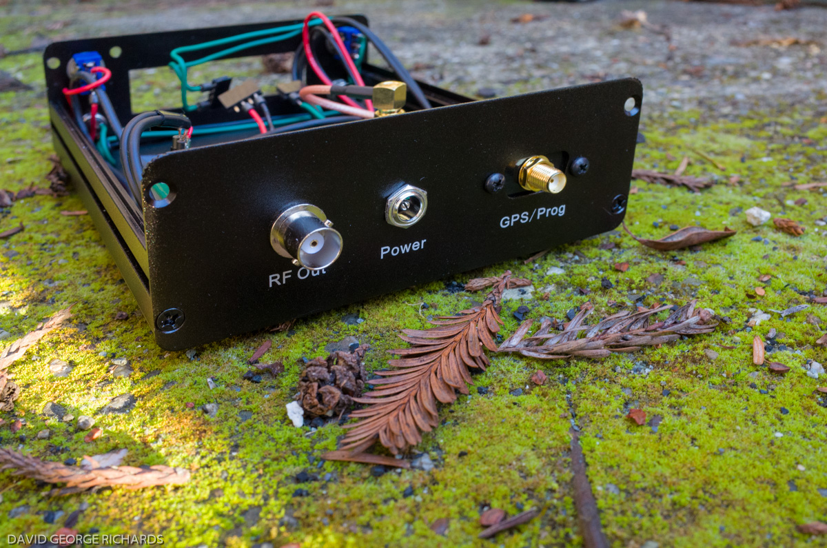
The obligatory “QRP rig set against a background of moss, morning sun, and dried leaves and bracken” shot –

I think the use of a drilled blanking plate to mount the SMA connector in the 9-pin D-sub cutout makes for a clean-looking rear panel. It was convenient that I had some black PCB material to hand –

Here’s a close-up of the logic board, showing how I routed the switch wires for the backlight just behind the top of the front panel. A 4-pin right-angle male header was soldered to the rear of the board for this purpose. You can’t see the whole header block, but you can see the silver pins sticking out, in between the bottom of the ICSP connector and the LCD –

All boards are now installed in the enclosure, and all hook-ups complete. I routed the green backlight switch wires just behind the front panel, held in place by some small pieces of foam, which I cut from the pieces that were used to pack the enclosure, and the chips in the kits. The wiring doesn’t look quite as messy now. I’d categorize this level of mess as being “some kind of partially organized mess”. See the resistor on the synthesizer board that is off-vertical? You can be sure that it was straightened before being shipped off to Fred 😀 –

All dressed up and ready for work –


No power is connected in these shots, so you’ll just have to imagine the blue backlit LCD screen. You’ll notice that I drilled holes underneath the switches for the locating tags on the switch washers. Ideally, these tags engage with holes drilled into a sub-chassis that resides behind the front panel, so that they cannot be seen from the front. With projects like this, where there is no sub-chassis, builders usually reverse these washers, or leave them out completely. I used to do this also, until a mishap a few years ago, where a panel-mounted pot swiveled round. One of the pot connections contacted something it wasn’t supposed to, inadvertently forward-biasing an LED with no limiting resistance, and blowing it. From that point on, I have drilled locator holes in all my front panels. Sure, it doesn’t look quite as nice but, to me, functional is nice-looking –


These pictures are getting a bit repetitive, but perhaps there’s some eager soul out there who is curious, and for whom one specific shot may show precisely that one detail which wasn’t apparent in the others –

Now you’d think the story would pretty much be ending here – and that’s what I thought too. After reading the documentation, and figuring out how to configure the U3S for WSPR operation. I had it on the air and almost immediately began generating spots on 17M. 17M is not as populated as 20, 30 and 40 are, but every day when the band opens, there is activity, and spots to be had. I was fairly happy, but noticed that after the initial warm-up period, my drift reports were 0’s and 1’s, with the occasional 2. I felt that could be improved upon. In the Builders’ Photos section on the QRP-Labs website, I saw that one gentleman had epoxied a short hex spacer to the top of the crystal can on his Si5351 synthesizer module, to help slow down the effects of temperature changes on the reference crystal. This was a cheap and easy fix, and it certainly didn’t hurt to try it. I used JB weld, which has a certain amount of electrical and heat conductivity –

With the synthesizer module installed back in the enclosure –


My drift reports went from 0’s and 1’s, with the occasional 2, to mainly 0’s with the occasional 1. A very satisfactory result for the 17M band.
After a few days of running the U3S all the hours that 17M was open, for a few days (I spend a lot of time at home), I programmed it with Fred’s callsign, and shipped it off to him. Unfortunately, something must have happened en route as, although he reports that it is getting a fix on, and tracking, a good number of satellites, it is not displaying the correct time, and not emitting RF when it is supposed to be WSPR’ing. I expect to receive it back from him this week, and will update this post with any developments. (EDIT – on receiving the unit back from him, I plugged it in, and found that it was working perfectly. A bit confused, I shipped it back to him, whereupon he reported that it was still acting up. He eventually discovered that the BNC cable he was using for the antenna connection was faulty. Problem solved!)
In the following picture, I forgot to insert the top 2 screws in the front panel. Other than that, here’s how it looks when complete. External GPS antennas are available for as little as $3 or $4 including shipping, from overseas sources on eBay. However, this was the first time I had purchased or used one, and wanted to ensure that I was getting one which would work satisfactorily. The GPS antenna from Adafruit was a few bucks more than the cheap sources, but I figured they wouldn’t sell a GPS antenna that didn’t work. Plus, they’re in NY, and I could get it within a few days. This is one neat little rig! I am not going into any detail on it’s various operating modes, as there is already an abundance of information available on this very subject. The purpose of this post was the same as the previous one – to act as a kind of show n’ tell for the assembly of this excellent kit from QRP Labs. With these kits from Hans, you get to choose exactly which options you want. If you’re on a very limited budget, you can get started in the world of QRSS/WSPR with the basic kit for $33 + shipping, and then add other options (GPS board, enclosure, extra bands, high stability module, etc) as you go. It’s an appealing approach, with plenty of opportunity for builders to customize their units to their own liking.


Dave, I haven’t had time to read the entire article because of some vision problems, but I will take a look tomorrow morning when my eyes are fresh. The photographs are, as they say, worth a thousand words! This looks like a fantastic project, but because of my weak vision, I probable won’t be building one in the near future. However, I can still make out the underside of a chassis containing terminal strips, half watt resistors, bulky caps and octal tube sockets! 😀
Thanks for the write-up and beautiful photographs.
73, de Mick Bradford – WB4LSS
BTW, this is my 50th year in Ham Radio!!
God Bless
“Terminal strips, half watt resistors, bulky caps and octal tube sockets.” You gave me a chuckle there Mick!
Glad you enjoyed the write-up, and congratulations on your 50th year as a ham. I’m a little behind you, with coming up on 40 years under my belt. Still – not bad for a young ‘un eh? 🙂
73,
Dave
AA7EE