
EDIT – If you’re thinking of building the Desert Ratt 2, although the pictures in this post are numerous and quite large, I do recommend reading all the text too, as I have included what I thought were relevant details on the construction as part of my narrative. Also make sure to read the comments and replies. Previous blog-posts have taught me that readers often ask pertinent questions, so you may be able to glean a little more information from them too. In fact, just before I wrote this, Paul NA5N made a comment which includes a usefiul piece of information about the 2 x 1,000pF (0.001uF) capacitors in the regen stage.
EXTRA EDIT – Please read the update at the end of this post, after the videos.
I’ve been wanting to build NA5N’s Desert Ratt regen ever since I first found his very attractively drawn schematic for it online. I then found the updated version, called the Desert Ratt 2, and a very good description of how the circuit works – all of these documents available on Paul’s website. What more could an avid regen builder want? Not much, it turned out. Late last year, when N2CX and N2APB dedicated an episode of Chat With The Designers to the Desert Ratt (and to the subject of regens in general), I just had to listen and of course, it fueled my interest in building the DR2 even more. The whiteboard for this particular episode of CWTD is here, and the podcast audio is here.
The WBR was a successful regen for me and while it worked well on SSB/CW, it didn’t seem to quite have the gain with AM stations. This makes sense, as a regenerative detector has to be set below the point of oscillation for AM reception, at which point it has less gain than when it is oscillating (which is where you set it for SSB/CW reception.) Even so, I had read that bipolar transistors tend to work better as regen stages for AM, as they have higher gain when not oscillating. The search was on for such a receiver, and this was one of the key deciding factors in building the DR2 for me. In fact, Paul has mentioned (I forget where I saw it, as I have done so much reading on this receiver) that the Desert Ratt doesn’t do so well with SSB/CW as it does with AM. My experience with it backs up this assertion, though it’s a pretty neat receiver for AM.
In particular, I wanted a receiver for covering the 49M SW BC band as although my Elecraft K2 covers a few of the BC bands, 49M is not one of them. There were a few things I found interesting about the design. The use of a phase splitter transistor to convert the single-ended output of the detector to a balanced output in order to drive the LM386 in differential mode was novel. Paul talks about how much RF is flying around inside regen receivers, and how the common-mode rejection of the 386 when used in differential mode can be advantageous in such an environment. I was also intrigued by the detector consisting of 2 germanium diodes – I think I was just looking for an excuse to build something with Germanium diodes again to remind me of my crystal-set building days as a kid 🙂
If you look at the schematic of the DR2, you’ll see that one of the changes in the design from the original DR is that instead of a variable capacitor, it uses 1N4004 diodes as varicaps. I have a bit of a “thing” for nice air-spaced variable capacitors, and I had in mind a nice Millen 50pF capacitor that I picked up on eBay for a very fair price last year. Combined with a 6:1 reduction drive, it made a good combination with a very useable tuning rate for tuning in AM stations.
Anyway, I’m getting ahead of myself here. I did make a few changes to the original schematic for my version, so allow me to introduce my rather wobbly circuit diagram –

The differences between my schematic and Paul’s are as follows –
– I added an RF attenuation pot at the antenna input. After building the DR2, I found that using a relatively short piece of wire indoors as an antenna was causing a lot of common-mode hum. On top of that, I wanted to be able to increase the signal level into the receiver with the use of my regular outside antenna (A 40M dipole fed with 300 ohm balanced feeder.) Using the attenuation pot allowed me to use the large outdoor antenna without overloading the receiver. Use of my outdoor antenna created enough separation between the receiver and antenna that the hum problem almost entirely disappeared.
– Earlier versions of the Desert Ratt included instructions for winding the coil on a plastic 35mm film canister and on an IC shipping tube. The DR2 schematic doesn’t include such instructions, but I wanted to use a toroid, so I experimented a bit and came up with a scheme that seems to work OK. I used a T68-6 former and the turns info is on my schematic above – a T50-7 would take up a little less space. More about this later.
– I had a few 2-position center-off switches that I wanted to use, so I used one of these for a bandswitch instead of the SPST switch in NA5N’s DR2 schematic. I had originally thought that using the 50pF tuning capacitor with no padding would make the upper limit of frequency coverage too high, resulting in too large a frequency swing in one band, but there must have been more stray circuit capacitance than I had anticipated, as the coverage with no extra padding was about 7.3 – 13MHz. This band became the center position.
– I was attempting to power the DR2 from my shack power supply, which is about 45AH of sealed lead acid batteries with a float charger constantly connected. This also powers my K2, and the DR2 was picking up processor noise from the K2, as well as a low-frequency “burbly” kind of noise of undetermined origin. The problem went away when I powered the receiver from a separate SLA. but I decided to add extra filtering to the power line anyway. I found that a 1mH choke as well as a 1,000uF electrolytic almost (but not quite) got rid of the unwanted interference on the power line. For good measure, I added a 0.01uF RF decoupling capacitor across the power line at the input connection.
– I added an AF preamp stage directly after the diode detector to ensure enough power to easily drive a speaker – even with weak signals.
– The inputs to the LM386 are the opposite way around from the way indicated in NA5N’s DR2 schematic. With the inputs connected as shown in Paul’s diagram, the LM386 emitted a loud screeching sound. Swapping the inputs cured this. I was not the only person who had this problem, as I discovered from this post in the GQRP Yahoo Group (you need to be a member of the group to read the post).
– I left pin 7 unconnected. I don’t understand the way that NA5N has it connected to the junction of the series resistor and capacitor connected between pin 5 and ground in his diagram. Most circuits that use pin 7 call for a decoupling capacitor direct from pin 7 to ground (usually about 10uF). This helps reduce large signal distortion, though Paul does say that in this application, it may not do a great deal to help and is therefore optional. I elected to leave it unconnected.
Now for some pictures. I didn’t want to spend a lot of time constructing an enclosure, so decided to make a simple PCB L-shaped chassis and build the circuit directly onto that. With the variable capacitor mounting bracket, it still ended up taking quite a while to construct though. All my projects begin like this, with the main components and control being laid out on the front panel, while deciding on the basic layout –

I’ll spare you the words at this point and apologize for all the pictures that are about to come. If you’re living in a remote area and are still relying on dial-up, then I feel a bit sheepish about the sheer number of images to follow! I’ve talked before about constructing enclosures from PCB material, so won’t repeat that information here. As well as constructing the chassis from PCB material, I also made a mounting bracket for the variable capacitor and a tuning pointer to attach to the reduction drive with 2 small screws – all from double-sided copper-clad laminate.


I applied several thin coats of lacquer from an aerosol spray. It was sprayed from a distance, resulting in a light, and stippled coating, which you can see in these pictures. I’d rather apply too light a coat than risk overdoing it. The downside of this is that oxidation will being to affect the appearance of the copper fairly soon. Oh well. The capacitor mounting bracket received a thicker coat. You can see the smoother, shinier finish.


I got the 6:1 reduction drive from Midnight Science. A number of others sell them, and one place that springs to mind is Mainline Electronics in the UK. They are the suppliers for Jackson Bros components (I think they have the rights to manufacture and sell the parts). They sell on eBay using the name anonalouise.


Look at that gorgeous variable capacitor!

Boy, was I glad to finish the chassis so that I could start work on wiring it all up. I decided to build the AF amp first and work backwards, my thinking being that the AF amp would be relatively straightforward. The act of touching the input with a metal screwdriver and hearing a hearty buzz in the loudspeaker would give a welcome psychological boost! If I started by building from the antenna end, I’d have to wait until the entire receiver was built before getting any clue as to whether it was working.
Here’s the chassis with the LM386 amp, the 2N3904 phase splitter, and the 2N3904 preamp built. As has been the case with all my projects since I started using then, I used W1REX’s wonderful MePADs and MeSQUAREs to build the circuit –


Here’s a close-up. The 2N3904 preamp is just below the 6:1 reduction drive, and the 2N3904 phase splitter is to the left of the LM386. The 100uF capacitor that decouples the supply line to the LM386 straddles it. I read that it is best to ground it to pin 4 instead of to some other point on the chassis to avoid instability, hence the reason for this placement. The other electrolytic that is straddling the chip is the 10uF capacitor between pins 1 and 8 that sets it to the maximum gain of 46dB. The black shielded cable connecting the AF gain pot to the circuit on the PCB is lavalier mic cable. It has 2 conductors, each of them in it’s own shield, which is ideal for wiring up potentiometers. It is fairly thin and very flexible. I use it in all my home-brew projects. I bought it from a local pro-audio store which recently closed down, so will now need to find another supplier.


In this view, you can clearly see the extra DC supply line filtering that I added, consisting of a 1mH choke in series with, and a 1,000uF electrolytic across, the DC supply. After seeing these pictures, I noticed that there wasn’t very much solder on the joint connecting the choke to the power jack, so I re-flowed the joint and melted a bit more solder onto it.


The power indicator LED’s main function is as a voltage regulator. NA5N marked the various voltages on his schematic for the DR2, and I chose an LED with a forward voltage drop to match those voltages as close as I could. A green LED in a variety pack I got from Radio Shack had a forward voltage drop of 2.1V, which seemed about right. The 1N4148 had a forward drop of about 0.65V.


The next stages to be built were the detector and impedance converter/buffer stages. The description of the DR2 on NA5N’s site gives more info on these stages (as it does for the whole receiver). I couldn’t be sure these stages were working, but bringing my finger close to the diodes resulted in a pleasing cacophony of stations in the headphones – and at a louder level than in doing the same to subsequent stages, so I figured there was some detection/amplification going on 🙂
I didn’t know how many turns I was going to use on the toroid, but using the calculator on W8DIZ’ site and an online resonant frequency calculator, I figured that 36 turns on a T68-6 should be a good starting point for the whole winding from pin 3 to pin 6. In Paul’s version, with the coils wound “traditional style”, the tickler winding was about 1/3 of the whole winding. Coupling between windings is tighter with a toroid than a “regular” coil, so I reduced the number of turns on the tickler. I found that regeneration was occuring at only about 25% rotation of the regen pot, so further reduced the number of turns. Using the turns shown on my schematic at the beginning of this post, the regen stage moved into oscillation at anywhere between 40 and 50% rotation on the pot, so I left it at that. For the same reason of tight coupling, I used fewer turns on the antenna winding too and because I am using an outdoor antenna, could probably have used even fewer turns.
The toroid was fixed to the PCB with nylon nuts, bolts and washers that I got from my local Ace hardware store.
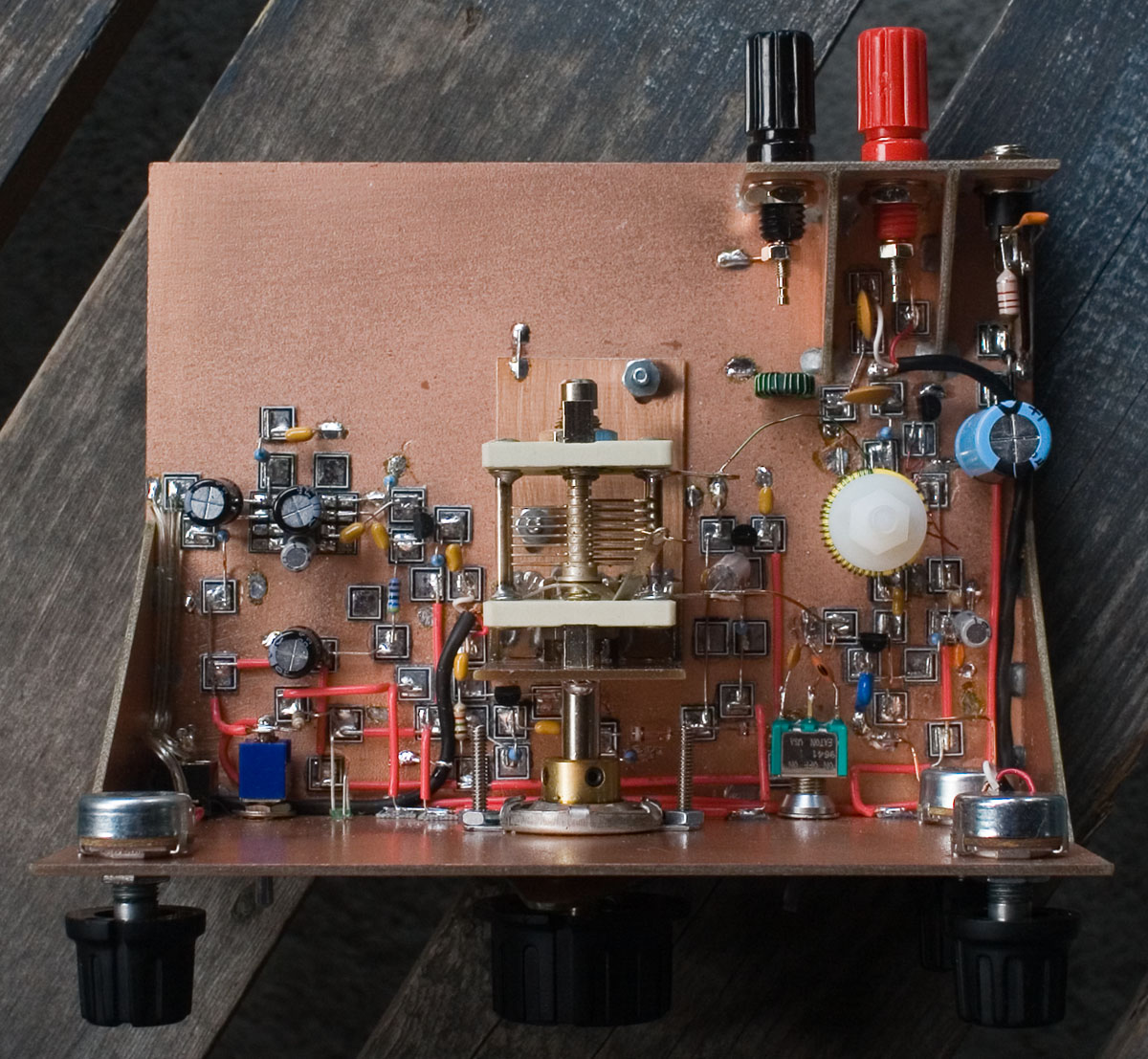
Here are some pictures of my Desert Ratt 2 with the circuit finished –


The red wires running along the back of the front panel are the regulated 2.1V and 2.75V lines. I would have run them on the main board but ran out of room due to lack of planning, so went vertical. Incidentally, although I refer to the 2 regulated lines as 2.1V and 2.75V, the exact voltages aren’t important. That’s just what they turned out to be in my case.
The RF amp and regen stages can benefit from transistors with high hfe. I got a cheap Harbor Freight DMM that measures hfe from an eBay vendor for under $6 including shipping. hfe varies depending on the collector current, but I was doing this mainly for comparative purposes rather than absolute values, so the fact that I didn’t know what value of collector current was used to measure hfe in this cheap meter didn’t matter. It just so happened that my 2N2222A’s tended to have higher hfe than my 2N3904’s, so I ended up using a 2N2222A that measured in at hfe = 203 for the RF amp, and a 2N2222A with hfe = 223 for the regen stage. The other stages don’t require high-gain transistors. NA5N talks about it in this post on QRP-L from 1999. Bear in mind that he was talking about the original version of the Desert Ratt in this post (just so you don’t get confused when he identifies the various transistors).

I did promise that I’d give a bit more detail on the toroid. Mine was wound on a T68-6 former. The main winding was 30 turns tapped at 27 turns from the top (3 turns from the bottom). The antenna coupling winding was 5 turns. All turns are wound in the same direction. I used 26 gauge wire, but the precise gauge isn’t important. 26 gauge was narrow enough to easily fit all the turns on the former, yet stout enough to lend some stability to the oscillator, as the toroid isn’t sitting close to the board, and the leads are relatively long. When putting taps on coils, I used to not cut the wire i.e. I would simply make a loop in the wire, twist it, tin the twisted part and keep on winding. Now I find it is easier to treat them as 2 separate windings connected together. If you can get heat-strippable wire, please do – it makes winding toroids so much easier and more pleasurable. I wound the first winding of 27 turns, stripped and tinned the end, then stripped and tinned the end of another piece of wire, twisted and soldered them together, and carried on winding the last 3 turns in the same direction (this is important). The separate antenna winding of 5 turns is also wound in the same direction. I’m afraid I didn’t write down (or if I did, I have since lost it) the lengths of wire used. I did notice that the turns calculator on W8DIZ’ site (linked earlier in this post) was quoting lengths that are too short for the T68-6 former. All you have to do is wind one turn around your former, measure that length, multiply it by the number of turns you’re going to wind, add an extra inch or two for the leads and, as we say in England, Bob’s yer Uncle and Fanny’s yer Aunt (meaning – you’re home free!) When winding toroids, I often find that the first 1 or 2 turns aren’t quite as tight as the rest so when I’ve finished winding, I will unwind one turn from the beginning of the coil, then wind an extra one at the end, to keep the total number of turns the same. Sometimes I will repeat that exercise a few more times until all the turns are nice and tight. For this reason, I use enough wire to leave several extra inches at each end.


The next picture shows an anti-hiss filter that wasn’t in the earlier pictures, which I tried and ended up removing due to a low-frequency oscillation it was causing at the higher volume settings. It was a series 0.01uF capacitor and 4.7K resistor connected from pin 1 of the LM386 to pin 5. From what I have read, too low a value of resistor or too high a value of capacitor can cause the oscillation. I have seen other anti-hiss filters that used a 0.01uF cap and a 10K resistor, so it is very possible those values would have cured my problem. However, I was near the end of the project and itching to move on, so I just removed it. You can also see the 0.1uF capacitors on the inputs of the IC that have been swapped over to stop the uncontrolled oscillation, and are now crossing each other. You may not have to cross these caps if you plan your layout accordingly –

Other than the problem with the loud screeching that was solved by swapping over the inputs to the LM386 (my schematic reflects the way the inputs were finally connected), the only other problem I had was with what appeared to be a defect in the 0.001uF (1,000pF) capacitor that leads from the tap on the coil to the emitter of the regen transistor. I wasn’t getting any regeneration at all but on replacing this capacitor, the circuit broke into a nice loud hiss when advancing the regen pot.
I do have one ongoing issue that I hope someone can shine a light on for me, and that is a loud crackling sound when adjusting the tuning capacitor. At first, I thought a dirty rotor connection was the problem, but it only happens when extra padding capacitance is switched in by the band-switch With no extra capacitance switched in, the tuning is smooth, but on the lower frequency bands, the receiver crackles when being tuned. I need to try bypassing the band-switch and soldering the padding capacitors into circuit in case the switch is the problem. I’ll report back when I’ve done further work on this.
Incidentally, the main tuning range on mine covers approximately 7250 – 13000KHz. Switching in a 47pF capacitor changes the range to 5825 – 8050KHz. I’m a bit limited with my receiver and test equipment here, so haven’t yet been able to determine the coverage of the lowest frequency band.
When first listening to the DR2, I had no idea what frequency I was listening to – only that I was probably somewhere between 5 and 12 MHz. I had no antenna connected (and at this point, hadn’t even built the RF amp stage) but started hearing CW. Lo and behold, it was Hank W6SX 180 miles away from me in Mammoth Lakes, CA. His CW signal was coming through well and in fact, this was the only time I have received CW in a satisfactory fashion on the Desert Ratt. There was no antenna – he was being picked up directly by the toroid. Any concerns I might have had about the sensitivity of this receiver would have been immediately allayed.
I know the main question that is probably on your mind is – how does it sound, and what is it like to use? How does it “handle”? There are some videos of my Desert Ratt 2 in action at the end of this post. Apologies for the poor video quality, but my only video camera is 10 years old (and has a faulty CCD sensor). You’ve probably read articles about regens that describe the many and subtle adjustments that need to be made when tuning a regen in order to coax maximum performance from it. If you haven’t operated a regen before or if it’s been a while, it does take some time to get the hang of getting the best out of it. As you get further away from the setting of the regen pot where it breaks out into oscillation you lose selectivity and gain, so you need to try and keep the control set just under the point of oscillation. Loud stations can overload the detector, resulting in audio distortion, so it’s worth keeping an eye on the RF attenuation pot too. Also, if the attenuation pot is set too high (too little attenuation), you may get breakthrough from stations on other frequencies. There’s quite a bit going on to keep under control, but if you manage to keep all controls adjusted well, you can coax some pretty decent performance out of the set. I think this is why regens appeal to some people – we are incurable knob-twiddlers!
Stability is easily good enough for AM reception and with a logging scale fitted to the front panel, I don’t think it would be hard to find specific frequencies, as the majority of SW BC stations stick to 5KHz channels. In my casual listening so far, I have heard The Voice Of (North) Korea on 9435 and 11710KHz, Radio Habana, Cuba on the 49M band, Radio Australia on the 31M band, coastal station KLB (South Korea) on 8636KHz, the BBC World Service (forget which band or frequency), China Radio International on 9790KHz, WTWW on 5830KHz, and a number of other evangelical Christian stations (sorry, I tune them out and don’t pay them much attention.)
To sum up, you can definitely have a lot of fun and engagement with the bands on this set. Being a regen, it is not the easiest receiver to operate, but you shouldn’t let that put you off. The best analogy I can think of is to reference the way that although an older British sports car may not have the finesse and performance of a newer sports model, it’s a lot of fun, and it’s lack of suspension gives you an exhilarating feel for the road that the more expensive cars cannot.

Please note that in the following videos, an MFJ-281 ClearTone speaker was used. My understanding is that this speaker has a slight resonant peak at around 700Hz (helpful for CW) and a relatively restricted overall bandwidth that is good for communications applications. This probably means that it’s not optimum for getting the maximum fidelity from an AM SW broadcaster (not that those stations have a lot of fidelity, but they tend to have a bit more than your average SSB transmission). On top of that, the audio was captured with the built-in mic in my old Canon A80 compact. Please don’t judge the quality of the Desert Ratt 2 audio from these clips. It’s better than this! I’m working on a few audio only recordings that will better demonstrate what the DR2 sounds like, and will put them up in the next blog-post (hopefully within a week or so).
Update – It has been about a year since I built my version of the Desert Ratt 2 and I feel compelled to provide an update. Whenever I first build a project I am often so thrilled that it works at all, that I tend to gloss over any shortcomings, particularly in my blog write-ups. Some of this is due to the possibility that any deficiencies are due to my layout and construction, as opposed to a problem with the circuit design. In the case of my DR2, I am still not sure whether the issues arise from the circuit itself or from my construction, as I have only built one of these. I did, however, want to document what I have observed, as my DR2 has laid on my shelf for the past year, largely unused, while I drag my WBR out and take it for a spin on a regular basis. Here are the issues I have observed –
* There is a lot of scratchiness in the speaker when tuning the DR2. This happens on some frequency ranges more than others, but it happens a lot. At first, I wondered if it was due to inadequate grounding of the rotor plates but I don’t think this is the case. There is a solder tab for both the rotor and the stator, and the rotor is grounded to the chassis by a direct wire. Also, it is a quality Millen variable capacitor, and it is clean (the oxidation has been cleaned off). I’m still considering the possibility that it as something to do with my variable capacitor, or the way that I have connected it.
* The set does seem to overload very easily on my outside antenna. Breakthrough from other frequencies is a common occurrence. This got me to thinking about the RF amp stage. The instructions call for picking a high hfe transistor to use in this position but thinking about this, I’m not sure why. Surely the purpose of an RF stage in a regenerative set is to provide isolation between the detector and the antenna, with gain actually being undesirable, due to the tendency of the detector to overload? The more I think about it, the more I think that different configuration for this RF stage would be more appropriate.
* Hum, though not always apparent, does still occur from time to time.
A commenter who goes by the name of Mast does mention that the tank circuit is very tightly coupled to the collector of the regen transistor. I’ll cut and paste his comments here, as I now wonder why I didn’t pay more attention to his input at the time,
“A nice schematic for general use. But the tank circuit is tightly coupled to the collector of the regenerative stage. You will suffer a lot from changing internal stray capacitances of the transistor when setting the regen level. And strong SSB signals will change these capacitances too, causing an unintelligible reproduction of SSB signals.”
At this point, the DR2 has gone back on the shelf while I move on to planning other projects, but I’d be very interested to hear what the experiences of others have been with this circuit. I know there are folk who found N1TEV’s beginner’s regen to be a little hard to tame – and the DR is based in part on that circuit. In contrast, both my WBR’s are well-behaved, and have been used regularly since I built them.

Dave,
As usual a fascinating post with some great detail and super pictures, I’m green with jealously, you make all your kits like works of art! …..OK, so who came up with the name “Desert Ratt” and why?
Love the videos, Not sure whether you’ll be pleased or not, but you certainly have the Beeb voice!
Completed the K2 and the KPA100 the other week, so far all is well and had some great contacts. A bit lost now I need to have another project, keep up the good work.
73s Richard M0AUW
Hi Richard –
I imagine that fairly soon, referring to a certain type of voice as being BBC diction won’t mean the same. When I first came over here, I didn’t listen to, or watch anything on the Beeb for years. Then when I started listening again, noticed that they were using a lot more hosts with regional accents. Accents in England are such an interesting study – there are even members of my family who grew up in the same household, yet whose speech is tinged with different regional variations! It’s all quite fascinating.
How are you liking that K2? It’s quite a construction project isn’t it! I want to build the 60M option for mine soon, partially in the hope that it will also allow me to listen to the 49M broadcast band. Not sure if the bandpass filters will stretch up that far though. As long as I am careful to beat AM stations against the sidetone and then subtract the frequenct of my sidetone (500Hz in my case), I can get quite passable AM reception, though it is fairly limited in fidelity due to the SSB filter on the rig.
So what are you going to build next, or are you going to give it a break for a while? By the time I finish building something, I’m usually a bit fedup of the workbench and keen to do something else for a while until my “building mojo” comes back 🙂
73 for now and please give the motherland my best regards 🙂
Geez, Dave – looks good enough to be a museum piece. Wish I had your talent!
Another work of art from the bench of AA7EE! Gorgeous work, Dave, I love your attention to detail. Sounds great, too!
A work of high-functioning art as usual, Dave. Well done!
Dave … your Desert Ratt is an absolute work of art. Excellent job and it sounds great. The circuit is optimized for AM detection over CW (a Charles Kitchen design), which is why the regen action is rather “soft.” As a result, it gives a much better sound and fidelity on AM compared to many circuits, which your videos demonstrate. The phase splitter transistor after the diode detector helps with the common mode noise, keeps from passing too much stray RF onward (common mode), and of course the extra 3dB gain from differential signals. I will check my versions and see what I can discover about the swapped phase on the LM386 causing oscillation. I don’t recall experiencing that, but my schematic may also be in error. Lastly, that .001 cap going to the coil tap is part of the oscillator feedback, and matched with the other .001 feedback cap, gives the balance for good AM regen action. If one of those caps has a high dc resistance or lossy, it will prevent it from oscillating as you noted upon replacing it. Good trouble shooting. Great photos also.
73, Paul NA5N
Thank you for the kind comments Paul. It feels good to know that my Desert Ratt has the seal of approval from it’s designer 🙂 That’s good info about the 1,000pF caps too. I didn’t know that they should be reasonably well matched. I’ll probably leave them as they are for now, but may try substituting a matched pair at some later point to see what discernible difference it makes.
Dave
AA7EE
I love how clean your work is. I use round pads made with the Harbour Freight Punch and do not make nice straight lines… ugly manhattan. I have really enjoyed your WBR project pics and once again this project is shear beauty. Great job. I am curious if you might lose the tuning noise with some shielding around the tuning capacitor… just a thought. The RF gain control is a great idea. When I hooked my pipsqueak up to the shack antenna all heck broke lose. I will see Rex at Hamcom in June, I need to buy some pads and give them a try. Thank you so much for sharing your radio journeys with all of us.
Mike KD5KXF
Thank you Mike – I tried making my own pads with a Harbor Freight punch, and the mistake I made was using double-sided board. They didn’t stick as well to the ground plane as they would have had I been using single-sided PCB material. Rex’s pads seem to adhere quite well. I roughen up the back surface of them with a craft knife before gluing them down, which also helps. One thing I like about the MePADS and MeSQUARES is the fact that there is a gap between the tinned copper area and the edge of the pad. This greatly lessens the chance of a short from the pad to ground, which happened to me once with my homemade pads when a whisker of copper bent down and touched the ground plane. It took me a while to figure out why my direct conversion receiver wasn’t working! Plus – Rex’s pads just look cool. Granted, they are a bit more expensive than making your own, but unless you’re really churning out the homemade projects, a single board lasts quite a while.
That’s an interesting thought about shielding the tuning capacitor. I go through a period immediately after I finish a project when I am happy to have finished and don’t want to do any more work on it. It will probably be a while before I try anything else, but I’ll bear your idea in mind. The thing is that it works perfectly, with no scratchy noise, when there is no extra capacitance switched in across the main tuning cap, leading me to believe it is something to do with either the padding capacitor, the band-switch, or the layout of these parts.
Let me know how you do with Rex’s pads. I’ll be interested to know how you get on with them – and what you build with them too. And of course – have a great time at Hamcom!
Dave
AA7EE
Another great piece, Dave. I really like the way you wired up the LED, too. Years from now, experts will point to the precise bends in the LED and nod knowingly, “You see this detail here? It proves it’s a genuine AA7EE!”
Frank – great to hear from you. It’s been a while, but I loved our phone chats. I hope the FT817 is still serving you well (if you still have it, that is).
Beautiful construction! Sivan Toledo
Hello, a question the regen to 40 meters, or please have the chassis dimensions. 73 de EA1EVB Date: Sat, 11 May 2013 06:39:54 +0000 To: juroma46@hotmail.com
Julian – my chassis dimensions are 6 inches wide x 3 inches high x 4.5 inches deep.
I’m not sure I understand your question about 40 meters. It does cover the 40 meter amateur band but is not a good receiver for amateur bands, as it does not demodulate SSB/CW well – it was designed specifically for AM reception.
This was my first ever homebrew project. I, too, had problems with the LM386 as shown in the diagram. I just substituted an LM386 amp shown in another design and it worked. A brilliant little radio, I thought.
Come to think of it, mine was a Desert Ratt 3 (as shown on Arnie Coro’s Radio Havana site).
Great blog! (Nice find for me.) I am not familiar with the copper laminate you used, but I am now. TNX. Would a build like this work with solid copper sheeting (I assume so)…did you consider doing so?
There’s no reason why solid copper sheet wouldn’t work Craig but I think you’d need a lot more heat to solder to it, due to the greater mass of metal. The appeal of PCB material for me is the ease with which it can be cut, drilled, and soldered to. I didn’t consider trying that – but now you’ve got me thinking about Drake 2B’s again, with those beautiful copper chassis!
TNX, Dave. I used copper sheeting years ago for an art project…nice stuff! eBay listed a 12″ x 36″ sheet for $45. Might be cheaper when I go to the city? Looking for something for my Pixie II…I’,m thinking copper or a nice wood box with a sliding lid (may put a ground plane inside?)? 73
A nice schematic for general use. But the tank circuit is tightly coupled to the collector of the regenerative stage. You will suffer a lot from changing internal stray capacitances of the transistor when setting the regen level. And strong SSB signals will change these capacitances too, causing an unintelligible reproduction of SSB signals.
Well it does have trouble with SSB, so maybe that’s why.
The WBR works best on CW/SSB and the DR2 works best with AM. Is there a type of regen that works well with both? Sort of an all purpose receiver? Your DR is really a work of art. Those square pads look so much neater than the round ones I punch out.
Paul – I’m really sorry that I waited so long to reply to your comment. I am still learning about regens so at the time, didn’t really have the answer to that question. I still don’t have a definitive answer, but I recently revisited my WBR and realized that it worked better with AM signals than I had previously realized. I just built a WBR for the 31M SW broadcast band and it is stable enough that I can enhance the reception of weak signals by putting the set into oscillation so that the set, in effect, recreates the partially missing carrier of the broadcast station. I believe this is called exalted carrier reception. Most of the time, I’ve been listening to AM broadcast stations with my new WBR set just below the threshold of oscillation and it works fine. The post on my new WBR is at https://aa7ee.wordpress.com/2014/06/24/building-a-wbr-regen-receiver-for-the-31m-broadcast-band-2/
My next regen will be based on the RF circuitry used in the WBR, with the exception that I’ll be using a more traditional unbalanced tank circuit (and an RF stage for antenna-detector isolation.)
Dave. Which regen receiver would you recommend for a first time builder?
Donald – if you have never built anything before, I’m not sure that I’d recommend a regen for a first project – particularly for a scratch-build. However, if you do want to build a regen, then I’d look for a kit with a PCB, and with which you don’t have to wind any coils. I’ve heard good reports about the Scout Regen from QRP Kits, but you do have to wind your own coil. I never minded coils, even as a beginner, but some do, so I’ll leave that decision up to you. Alternatively, the Mark Regen from Walford Electronics in the UK seems like a good kit – and it uses pre-wound Toko inductors. I have not seen one in person, or built one, but Walford Electronics are well-thought of and I have heard good things about the kit.
Oh – I just thought of another idea – the Ozark Patrol from 4SQRP – http://www.4sqrp.com/ozarkpatrol.php
Apologies if this was a rather rushed reply Donald, but I hope it has given you some food for thought. Please do ask if you have any more questions,
Dave
AA7EE
A good beginner’s regen is at http://www.b-kainka.de/bastel3.htm. It consists of a BJT square-law detector and a Q-Multiplier with a minimalistic differential pair. These two stages have been connected onto a tap of the main tank coil.
Hi Dave- I must know…what kind of drill and bits did you use to make the various-sized holes in the enclosure front panel? Lovely work.
Brian, KK6JTZ
Brian – Thank you for the kind words. All holes made with a manual hand drill and regular high speed steel drill bits.
Dave
AA7EE
mine doesn’t work. most confusing: how to wind T1. Who can help?
news from the bench – I took the schematics by NA5N’s Desert Ratt-2 in which is an error: pin 7 from the LM 386 leads directly to juction R12 + C20. Doesn’t work! Ref. to datasheet from Texas Instruments Dave took it very nicely to leave it n.c. To me I decided to take another 0.1uF from pin 7 to GND. that’s it. cheers folks and enjoy – Raimund, DL1EGR & the group
I’m glad you got it working Raimund. Although I left pin 7 unconnected, it is a good idea to bypass it separately, to avoid instability. Most LM386 circuits use a capacitor directly from pin 7 to ground of value somewhere between 1uF and 10uF. I recommend adding this capacitor.
Hello Dave,
I am JA5NAF Kenji Kitagawa.
Looking at your production article, I also made Desert Ratt – 2.
I am grateful to you and report on production.
Sorry for the Japanese page.
Please translate and see.
http://iyo.890m.com/ja5naf/
Kenji – good idea on making the RF amp a grounded gate type for unity gain. One of these days, I may drag out my Desert Ratt 2 and make that change. Thank you for the link to your web page and the build of your DR2!
73,
Dave
AA7EE
Dear Dave: As usual, amazing your work. I have troubles when used reduction drives without an isolating couple. Perhaps the drive make bad contact against chassis, and become noisy when tuning. I used a small section of plastic tube (Gas tube line from my motorcycle).
I noted you fed the amplifier with low voltaje. Perhaps your dynamic range will be better if you feed it with 12 VCD and let the 2V7 to the detector only.
Closing, I seen you dont integrate the audio signal at the output of the diode doubler. A small 47 nF in paralel with the 10K resistor will decouple the RF from this point, where only audio travel. The pin 7 of the LM380 is for a decoupling interstage capacitor and will help to a good audio too.
Is the best version of the Desert Rat I have seen. Thanks for sharing it.
Regards. Edgardo LU1AR
Edgardo – thank you for your comments. I am taking another of my (increasingly regular) breaks from ham and SWL radio, but will read your comments again with interest when I return. Thank you and 73!
Dave
AA7EE
Good day, I would like to know where you bought the nice knobs and the variable cap
I am in SOUTH AFRICA and we battle to get it
73
ZS4F
Pierre –
I got the variable cap from eBay a while ago. I have bought quite a few nice variable caps from eBay sellers over the years. It’s a case of looking often, and being patient. As for the knobs, they came from a US electronics distributor called Mouser. They do ship to South Africa, though I’m not sure what the cost of shipping is. The Mouser product # for the smaller knob is 450-2035-GRX and you can find it here –
https://www.mouser.co.za/ProductDetail/Eagle-Plastic-Devices/450-2035-GRX?qs=%2Fha2pyFadujxJqyRDzNl5UB46t0cKMW%252B8kBHr6wmOAXC8a3sGzYy2A%3D%3D
The larger (tuning) knob is Mouser product # 450-2039-GRX and you can find it here –
https://www.mouser.co.za/ProductDetail/Eagle-Plastic-Devices/450-2039-GRX?qs=%2Fha2pyFaduioS%252BlFGCf74cNFOkSCBoca%2FjGPLQsFbbdRf1TMPcuD0A%3D%3D
Incidentally, there is a matching knob in the same style that is a little smaller than even the smaller knob. It is product # 450-2034-GRX. I have found it useful for projects with small front panels and tight layouts. It’s product page is here –
https://www.mouser.co.za/ProductDetail/Eagle-Plastic-Devices/450-2034-GRX?qs=%2Fha2pyFadujsrdns6xZmj15s9d8%2FPu5cYB5gSNJo7dnw%2FbQyjx%252BXlw%3D%3D
Once you’ve factored in the cost of shipping, I’m guessing that it’s probably quite a bit to spend, just to get your hands on some knobs. There must be a more cost effective source of knobs in SA, though I’m afraid I’m not familiar with electronics suppliers in your part of the world.
Best of luck and 73!
Dave
AA7EE
Good day,
I would like to know where you bought the KNOBS and the variable caps from?
I like to build AM receivers, great job.
PIERRE
ZS4F
73
THANK YOU VERY MUCH DAVE
PIERRE
ZS4F
73
Reduction drives has´nt been available in Sweden in decades. Pity and shame!
Hai, Whad a great and very looking good reg, receiver, and how it all looks and how you build it just great! wouter eisema, ( The Netherlands)
Thank you Wouter. 2 days ago, I was listening on 20M and heard a CQ from NA5N, the designer of this regen. I called him back and had the pleasure of working him!
73 for now,
Dave
AA7EE