

Growing up as the youngest of 4 boys, I was well positioned to receive all the hand-me-downs. Although that might sound as if I just ended up with second-rate stuff, that was not the case at all. I inherited a lot of great things from my older brothers. I couldn’t have cared less that they’d had them before me. The stash consisted of all sorts of board games, Dinky toys, and books, as well as something that would fuel my imagination for many years to come – a crystal set. My very own crystal set! Manufactured by Ivalek, this little beauty sat in it’s white plastic case by my bedside, delivering quality programming from the BBC 24/7 –
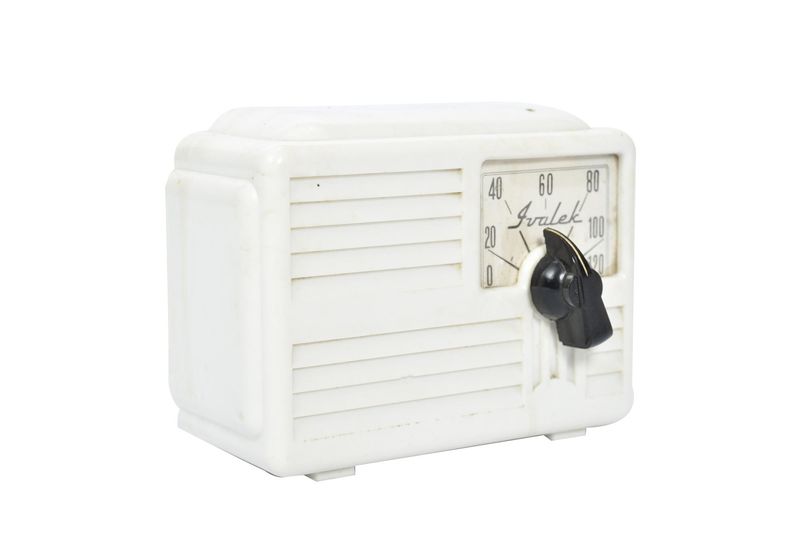
In truth, in the big world of crystal sets, this little mass-manufactured set wasn’t a very good performer at all. In fact, I’d go as far as to say it was pretty awful, having the following schematic, which I don’t think should ever be used for anything other than a teaching tool, but not a practical build –
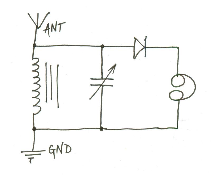
The above is almost the simplest crystal set you can build. The Ivalek also has a switch that switches in extra inductance for the long wave band, but we’ll ignore that. The main problems with the above schematic are –
- The antenna is not impedance-matched to the coil, so it will load it down, reducing Q and therefore, selectivity.
- The diode is not impedance-matched to the tank, loading down the tank, and also affecting Q, and selectivity.
- The headphones may not be matched to the diode affecting – yes, you guessed it, circuit Q and, therefore, selectivity.
A lot of simple “toy” crystal sets that were marketed to kids in the 50’s, 60’s, and 70’s employed this simple schematic and, as a result, we all got the idea that crystal sets were fun, but not very good, and not to be considered as a “serious” receiver for extended periods of listening. In my case, making things worse, was that I thought the telephone earpiece I was using was high impedance. 8 year-old me had no idea the impedance was actually closer to 150 ohms. The end result of all of this was that my crystal set had very broad tuning indeed. On the other hand, it was very loud, because we lived only a few miles from the BBC Droitwich transmitters. The longwave transmission, on 200KHz at the time, was 500KW in power, and covered most of the UK. The medium wave signals, though not quite as powerful, were certainly not QRP either.
The lackluster performance of my Ivalek crystal set didn’t put me off. I just thought it was the neatest thing that I could leave it on all the time, and would never have to change the batteries. Plus, I had plenty of chances to listen surreptitiously under the covers at night, when I was supposed to be sleeping!
I also had this magnificently compelling book –
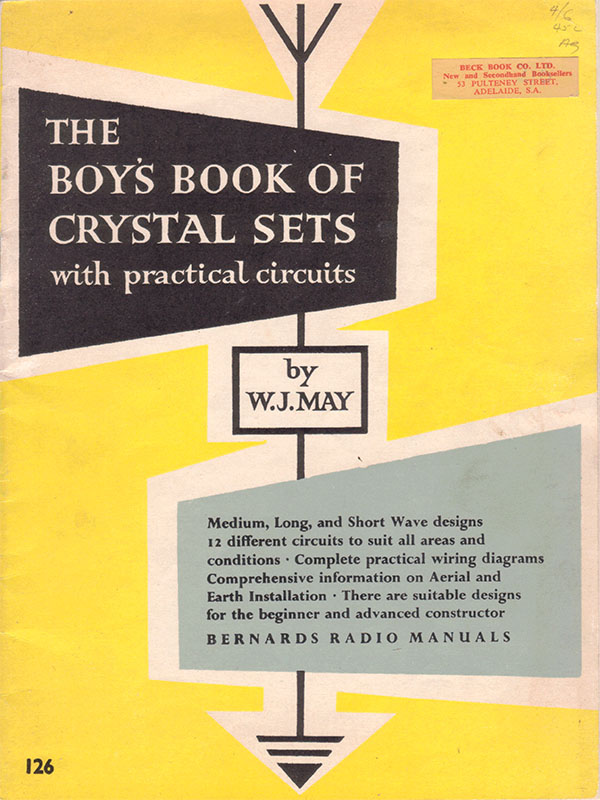
The Boys Book of Crystal Sets contained construction details for 12 different sets of varying complexity and, presumably, performance. The young me spent hours and hours gazing at all the articles and schematics, and thinking how grand it would be if I had an air-spaced variable capacitor or two, some litz wire to wind a coil with, and an empty tobacco tin or chassis, to build my crystal receiver in. I’d be the king of the hill! But an 8 year-old boy living in the countryside in the early 1970’s didn’t have the means to procure such elite and specific luxuries, so I settled for reading each article a couple of hundred times, and day-dreaming.
About 10 years ago, I came across a web-site belonging to Jim Frederick W4LF. Jim is a big fan of Cushman scooters, which are uniquely American motor scooters that boast an earnest following of enthusiasts. The Cushman Scooter company was formed in Lincoln, Nebraska in 1903, and produced their last scooters in 1965. The majority of Jim’s site is given over to discussion of these machines. As you might guess, it wasn’t these that interested me, but a single page on Jim’s site that is dedicated to another of his interests – little radios and crystal sets. On this page Jim shows pictures, with brief descriptions, of the neat little radio receivers he has built over the years. They include regenerative receivers, crystal receivers, and some amplified crystal receivers. I loved not only the fact that he was using double-tuned circuits with, in many cases, adjustable capacitive coupling between the tank and the detector for greater control over the selectivity of the circuit. I also really appreciated the attention paid to the casing and overall appearance of the final product. These were some really appealing little receivers!
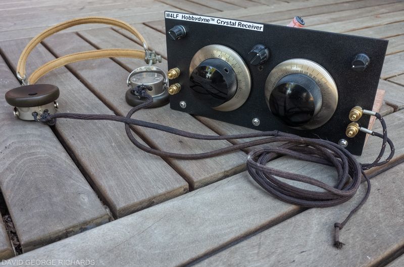
Recently, I had the honor of assembling a pre-production beta build of the 3rd generation of Jim W4LF’s Hobbydyne™ Crystal Set Receiver kit. I won’t go into details of the build here, but the kit should be available soon, at this site. If it is not yet active, save it in your bookmarks, and check back later. When the site is up and running, it will be the place to get more info on this kit.
I’m very happy with the end result, and I hope you’ll agree that it is a very good-looking little crystal set, with it’s African mahogany base, and garolite front panel –
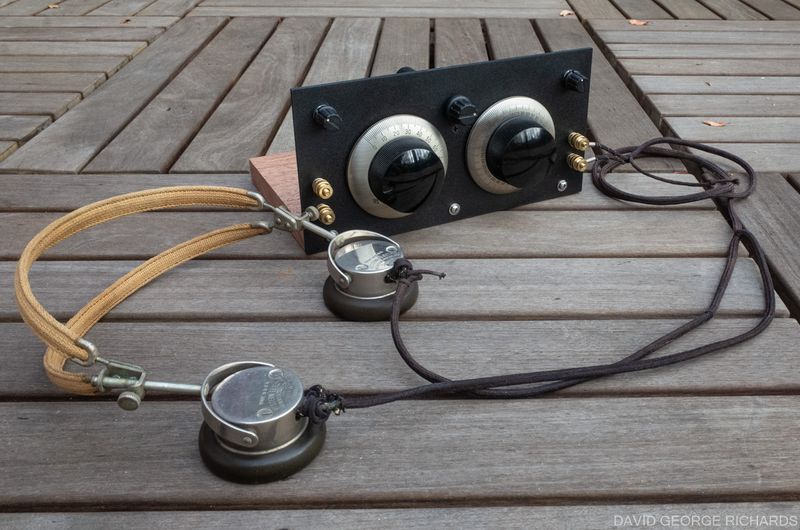
From top left to top right, the knobs are – a rotary switch to add extra capacitance to the antenna tuning capacitor, for help in tuning different lengths of antenna, the variocoupler, which controls the coupling between the coils, and also the selectivity and, on the far right, the Hobbydyne™ selectivity enhancement control. The circuit of this set is heavily based on, and very similar to Jim’s original Hobbydyne™ circuit, which was featured in Dave Ingram’s column in the Nov 2005 issue of CQ Magazine.
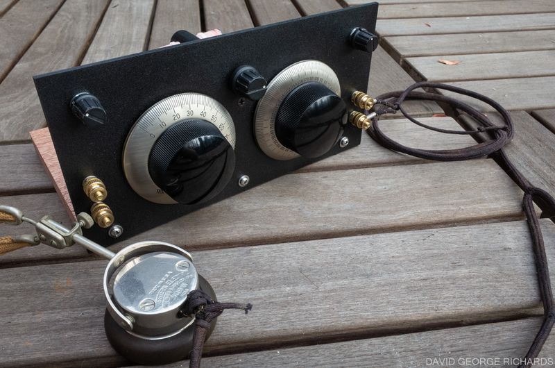
The brass binding posts on the left are for antenna and ground connections, and those on the right are for the headphones.
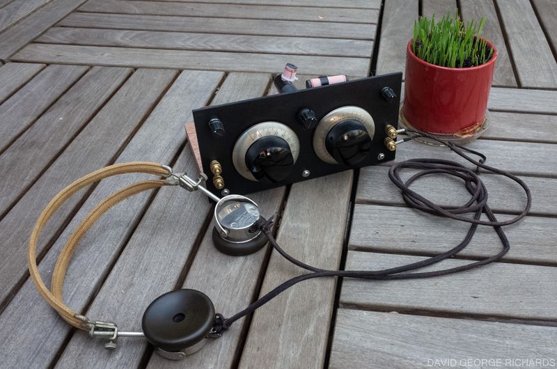
The headphones are a set of Western Electric 509-W’s. They’re about 100 years old and work well, if you’re looking for a set that will plug directly into a crystal receiver without the need for impedance matching.
As soon as I had constructed Jim’s Hobbydyne™ kit, I started looking for two things in quick succession –
- A good set of high impedance headphones and
- An impedance matchbox, to experiment with different types of headsets/headphones.
While planning the construction of an impedance matchbox, to match a variety of crystal set detectors with a range of headphone impedances, I also kept an eye out on eBay for headphones, and the necessary parts to build a sound-powered headset. That is the subject of a whole new post, which will come after this one. The construction of just one crystal set, which you’d think would be a simple affair, while not quite turning into a rabbit hole, was certainly becoming quite involved!
I have a habit of over-estimating how involved I’m going to become in pursuits when still in the beginning stages. For instance, when digital photography was really starting to take hold, in the early-mid 2000’s, I decided to get back into photography, which had first grabbed my interests as a teenager. This time though, I was an adult with more disposable income. I went a bit hog-wild, buying a nice camera and a whole slew of lenses, accessories, and even some studio lighting equipment (not the cheap kind either). Although I had a lot of fun with all that gear, I realized over the next few years that I had overbought, and spent a fair bit of time selling all the photo accessories that were surplus to my needs, eventually distilling them down to only the essentials. All this is a prequel to me saying that if you want a crystal set which performs well but, being realistic, you’re not going to want to eke out the very last drop of high performance from it, you might be happy with connecting a set of high impedance headphones directly to the output of your new crystal set, and leaving it at that. I wanted to be able to test out a variety of different types of headset, headphones, and earbuds, so an option that offered a variety of output impedances was definitely on the cards for me. A selection of different input impedances would also allow experimentation with other crystal sets in the future.
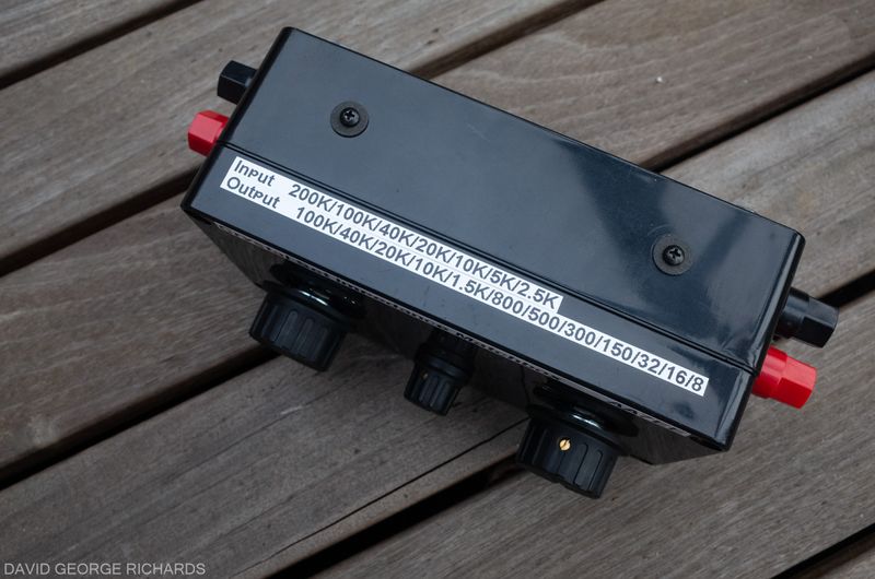
Crystal set builders have used various methods to match the diode detectors on their receivers to headphones over the years, with a variety of transformers being used. Darryl Boyd’s very informative site at crystalradio.net has a section devoted to detector to headphone impedance matching, with a number of approaches detailed. One of the most recent solutions has been the very useful Bogen T725. More recently, an auto-transformer has come onto the market that is wound specifically for the needs of crystal set builders. The KPB-02 auto-transformer has both inputs and outputs (on the same terminals, being an auto-transformer) of 200KΩ, 100KΩ, 40KΩ, 20KΩ, 10KΩ, 5KΩ. 2.5KΩ, 1.5KΩ, 800Ω, 500Ω, 300Ω, 150Ω, 64Ω, 32Ω, 16Ω, 8Ω, and 4Ω. It was custom-made for our needs and, as such, has input and output impedances that satisfy any possible need a crystal set builder could conceivably want. Look for the KPB-02 on eBay, being sold by seller mkmak222. This auto-transformer formed the basis for my all-purpose crystal set impedance matchbox.

On the input of the box is a Benny, consisting of a 0.1µF capacitor and a 500K audio taper potentiometer. The Benny is named after Ben Tongue, who wrote a series of detailed technical articles on the subject of crystal sets, which, taken together, probably represent the most detailed analysis of this type of receiver architecture ever published. Ben is no longer with us, but you can find his articles here. You might want to save them all just in case one day, they are no longer hosted anywhere online. He talks about the Benny in article 01. Very briefly, it helps to reduce audio distortion on strong signals, by equalizing the DC and AC audio loads on the diode detector.
Both rotary switches are 12 position types but on the first one, on the input side, I only used 7 positions. Some switches have an adjustable stop, so that the switch will only rotate to the number of positions set by the user. You’re highly unlikely to encounter a detector with an impedance lower than 2.5K, so there is little point in going any lower. The last two positions, of 5K and 2.5K, are included in case a device such as a MOSFET is used as a detector; with diode detectors, the impedance is going to be somewhere in the 200K to 10K range.
There is more potential for variety when it comes to the output impedances, so you’ll probably find yourself using all of the positions of a 12 position switch. There are 20 position switches available, which would allow a builder to make all of the 17 impedance taps available. However, they are a bit pricey. On top of that, the one I found didn’t have a lug to prevent a loose switch from rotating, and I like to make use of those.
In my matchbox, all of the taps from 100K down to 1.5K were utilized. I found that range covered all of the vintage high impedance ‘phones I tried out, as well as the piezo earpieces in my collection. Kevin Smith, when building his impedance matchbox, divided his ranges a little differently from mine. His ranges were 100K down to 10K for magnetic and piezo ‘phones, 1.5K down to 300 for sound-powered headsets, and 32 to 8 for modern low impedance ‘phones and earbuds. The sound-powered headset that I put together turned out to have an AC impedance at 1KHz of about 3K, so the middle impedance range in the hundreds of ohms wasn’t needed. When describing his impedance matchbox, Kevin talks about the lack of a need for exact impedance matching, due to a listener’s inability to distinguish much of a difference in volume when the mismatch creates a volume difference of 3dB or less. He calls it “the 3dB slop”. If you build your own matchbox you will notice, when stepping through the impedance taps, how for any given set of ‘phones, there are several switch positions that give acceptable and almost equal volume. Looking at the schematic above you can see how, if you did happen to have a headset with an impedance of 800 ohms, for example, the closest tap available at the switch, is 1.5K, which would still give an acceptable match. Likewise, if your headset had an impedance of 500 ohms, the 300 ohm position would be adequate.
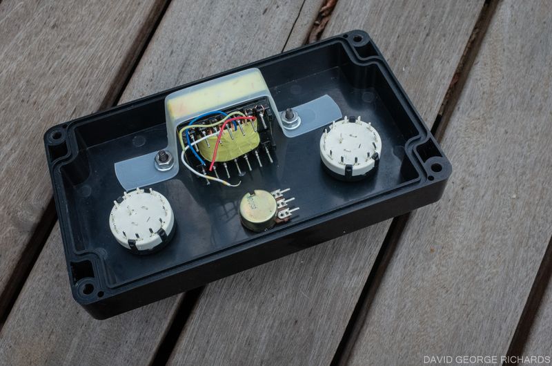
The KPB-02 auto-transformer doesn’t have a built-in mounting bracket. I cut a strip of flexible plastic from the top of a small storage container and used to it mount the transformer to the lid of an ABS plastic project box –
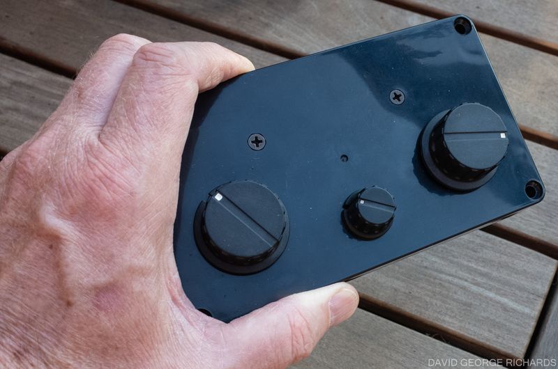
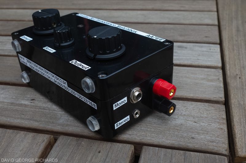
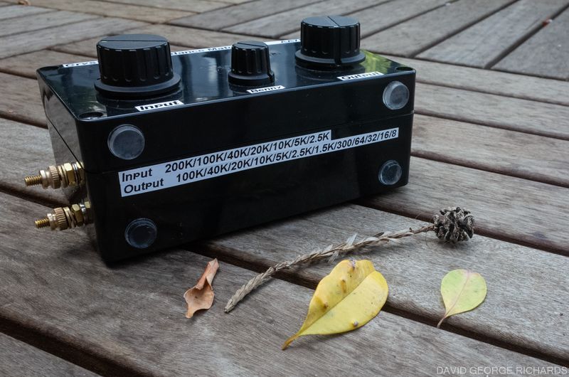
In the next photo, you can see an earlier version of the matchbox, which utilized chunkier, more modern binding posts. They are the type often marketed for speaker connections. I discovered that it is not as easy to connect the bare wire ends of the metal tips often used on vintage headphones to them, as it is with the more traditional style of brass binding post. I also ended up changing some of the impedance taps from the ones shown in this photo. There are vinyl bumper feet on two sides of the box, so it can be used in two different orientations –
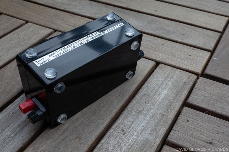
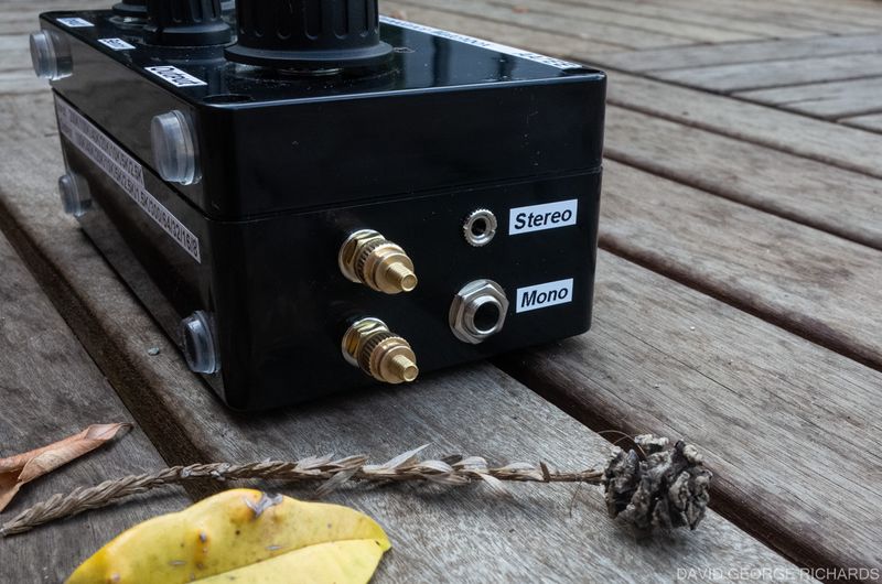
Although a single pair of binding posts are used for the input, more output options are provided, in the form of a 1/4″ jack wired for mono, and a 3.5mm jack wired for stereo headphones, with the velements placed in parallel, in addition to the binding posts for the metal pins on vintage headphones as well as bare wire ends –
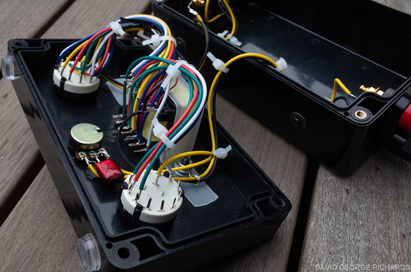
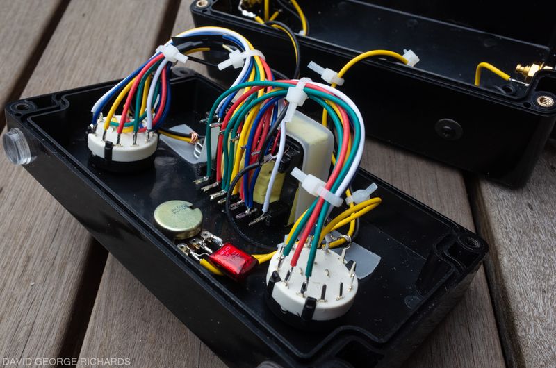
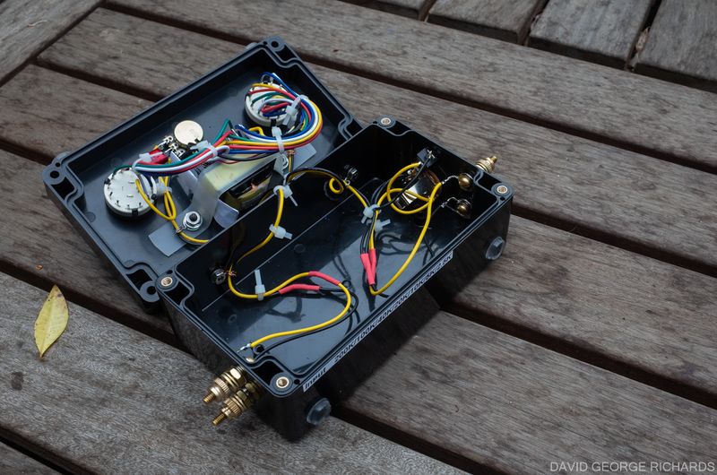
The internal wiring in the first version of this matchbox, before the wiring to the impedance taps was changed a little –
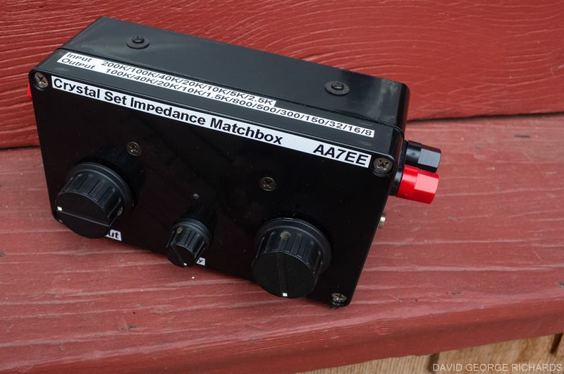
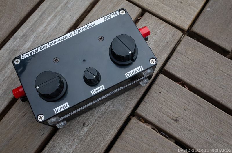
On realizing that traditional brass binding posts were going to work better in this application, I took out the speaker posts, made a trip to Ace Hardware, bought the appropriate brass hardware, and fitted the impedance matchbox with 2 handsome sets of brass binding posts. I also changed the wiring to some of the impedance taps on the transformer. Note the new labeling –
Unfortunately, swapping the location of the binding posts necessitated a lengthening of the wiring, and made it a bit more untidy. Nevertheless, I wanted brass binding posts on this matchbox, and am glad I added them –
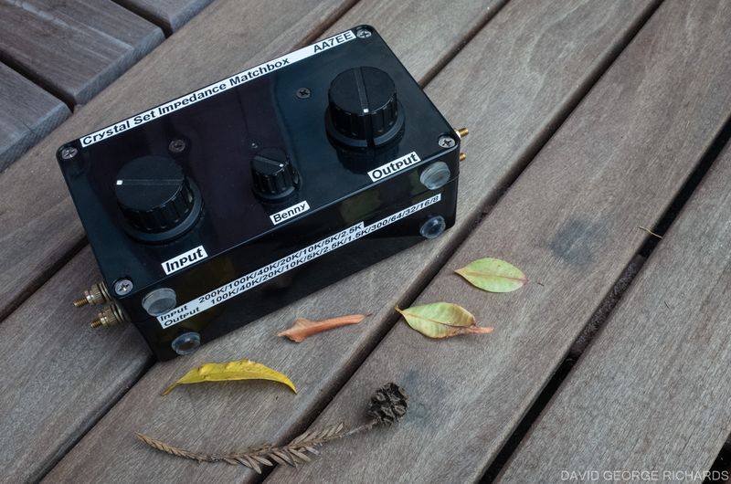
The brass nuts on these binding posts are called brass flanged knurled-head thumb nuts on the McMaster Carr site, though I got mine from my local Ace. The 3.5mm jack is wired so as to place the 2 elements in parallel. I did this so that they would be fed in phase. If you use the ring and tip connections to feed them in series, you will end up feeding them 180° out of phase, though I’m not sure if that makes a noticeable difference in practice. The 1/4″ jack is wired to the sleeve and the tip only, for mono jacks. Another change I made, was to place the binding posts on the end of the enclosure that faces the operator. In the previous version, they were at the back, causing the metal tips of vintage headphones that were connected to the binding posts, to foul the two jacks. Small ergonomic details like that make quite a difference to the usability of a piece of gear –
One thing I noticed, stepping through the different output impedance positions for a given headset, was that although nearby switch positions to the optimum one produced almost exactly the same volume, the tonal quality changed. If the switch position is set higher than the headset impedance, higher audio frequencies are favored. As you rotate the switch through the optimum position to impedances that are lower than optimum, more bass response is favored. This could possibly be used with very weak signals, as a switch position that favors higher frequencies could, if copy was very marginal, perhaps improve intelligibility enough to be able to ID a station.
An impedance matchbox is a useful piece of gear in an experimental crystal set receiving station. It makes constructing subsequent crystal sets easier, as the builder doesn’t have to keep replicating the audio circuitry after the detector diode.
In the next post, I plan to show you the various vintage as well as modern headphones and headsets that I tested with the Hobbydyne™ Crystal Set and impedance matchbox combination.
In the meantime, more information on Crystal Sets, and DX’ing with them, can be found in the following, as well as the various individual blogs on the subject (I’ll let you find those!) –
The Crystal Radio DX Group on Facebook – a group founded and run by Steve VE7SL. Intended specifically for discussion of crystal set DX listening events, as well as circuits and techniques specific to DX’ing with crystal sets.
The Crystal Set Radio Group on Facebook – a larger group, for general discussion of crystal sets. If you are a newcomer to the world of crystal sets, this would be a better group for you than the previous one.
The New Radio Board – intended as a new version of the now defunct (and much missed) Radio Board Forum, this board contains discussions of construction of several different types of receivers, including solid state radios, tube radios, and crystal sets. Links to the different topics can be accessed from the lists of hashtags.
A good introduction to the subject of crystal sets can be found in this engaging talk given by Al Klase to the New Jersey Amateur Radio in 2022, titled ,“Understanding and Building Crystal Radio Sets”. The graphics to go along with the talk are here.

As always, an excellent article. My own journey to becoming a radio ham started with a crystal set kit bought as a Xmas present from a Sunday newspaper when I was about 11. For the antenna I used the bedsprings and the earth was a central heating radiator. I may just have to construct another having read this.
Thanks Andy – I recommend a design that uses a double-tuned coil, with a way of varying the spacing between the coils (two coils and two variable caps). You can get good control over the selectivity by doing it that way!
Great read Dave and much information !
Thanks !
Jim WB4ILP
I hope it was helpful Jim. That little KPB-02 auto-transformer was designed specifically for crystal set use, and is a very handy transformer to have around!
Dave
AA7EE