
When 4SQRP brought out a version of the David Cripe NM0S-designed Hi-Per-Mite Filter, I noticed that it could be configured to give up to 50dB of gain. Like many others, I’m sure, my next thought was that it would make the process of building a simple direct conversion receiver even simpler. I decided that at some point, I needed to use this little filter board as the audio chain in a direct conversion receiver for CW. I wanted to see for myself how it would sound.
In the meantime, my preoccupation with direct conversion receivers continued, as I embarked on building a G3WPO/G4JST DSB80. The receiver in that DSB rig uses an SBL1-8 DBM. That particular mixer package is out of production, but I used an ADE-1 and was pleasantly surprised by the receiver. I had some problems with the TX section, so put it aside and started building a ZL2BMI DSB transceiver. I’d known about this little rig for a while from the pages of SPRAT, but a comment on Twitter from NT7S encouraged me to have a go at building it. The receiver is a simple NE602/LM386 combination with just a single-tuned filter on the antenna input. Of course, the receiver is not THAT simple, as each chip contains more complex circuitry, but the schematic at the chip level looks almost too simple to work. As with the DSB80, I had problems with my ZL2BMI rig transmitting a sizeable residual carrier, but was surprised that the receiver sounded pretty good. The seed was sown…..
The ZL2BMI DSB rig was actually only the second time I had built an NE602/LM386 direct conversion receiver. The first was about 20 years ago when I bought a kit for the Sudden receiver on 20M. At the time, I wasn’t that keen on it and it soon ended up in pieces. I’m not exactly sure why I wasn’t taken by it, but I think it was a combination of factors. Firstly, I was living in an apartment in Hollywood with no outdoor antenna and was using just a short length of wire indoors as an antenna. It’s also highly possible that band conditions weren’t great, but I just remember not hearing many signals and also not liking the fact that a half-turn of the variable capacitor covered the entire 20M band. Because of this one not so great experience, I have since harbored a bias against using NE602’s in direct conversion receivers, an attitude that I now realize was unfair.
After achieving only partial success with both these rigs but enjoying the fact that the direct conversion receivers in both of them worked quite well, I wanted to build a simple receiver and use the Hi-Per-Mite kit that had been sitting patiently on my shelf for the last few weeks.
Look at the schematic for any NE602/LM386 DC receiver, and they are almost all the same, differing only in whether they use a crystal, ceramic resonator, or free-running VFO for frequency control, whether they have a single-tuned or double-tuned antenna input filter, or whether they use a differential or single-ended audio input. The circuit is so simple that there is only so much room for variation, but there were a couple of things I had in mind for my mine. While the receiver portion of the ZL2BMI rig only has a single-tuned filter on the antenna input, I wanted to do what G3RJV did with the Sudden, and place a double-tuned filter there. It’s an easy thing to do, and living in a built-up urban area, I have a lot more RF around me than ZL2BMI does when he’s using his rig in the bush, so a bit of extra bandpass filtering certainly couldn’t hurt. The other decision to be made was the method of frequency control. I was curious to see how the internal oscillator in the NE602 would work as a free-running VFO. My apologies to you folk who have built umpteen simple NE602-based receivers and have-been-there-and-done-that. I guess I need to get this out of my system! Another thing that I had seen in other circuits but hadn’t tried was the use of a 1N4001 diode as a varactor. Some call it the poor man’s varactor. Sounds like it was custom-made for me!
So that was my configuration – double-tuned input filter (just like the Sudden) and a free-running VFO tuned with a 1N4001 diode. From what I’d read, I knew that I should be able to get enough capacitance swing from the 1N4001 to cover at least the bottom 30-50KHz of 40M. Here’s what I ended up with:

There’s nothing original in this schematic but as you’ll see soon, it did turn out quite well, so I decided to name mine “The Rugster” after my cat, whose full name is Chloe-Rug, but who gets called several different variants of that name, of which “The Rugster” is one. For the input bandpass filter, I used the vales of L and C that are used in the GQRP 40M Sudden Receiver. The pre-wound inductors in that design have a value of 5.3uH. I decided that I wanted to use T37-2 cores, so I used the calculator on W8DIZ’s site to figure out that I’d need about 36 turns on a T37-2 core to give 5.3uH of inductance. I fiddled around a bit with the values of the parallel fixed capacitors before settling on 47pF for those. I had originally thought that a higher value of around 68pF should work, but that didn’t put the peak of the filter somewhere in the mid-range of the adjustment of the trimcaps. Some experimentation revealed that 47pF fixed caps achieved this. Your value may vary depending on what value of trimcap you are using. For the VFO inductor, I found a design for a 40M DC RX on the internet that was tuned by a 1N4001, noted the value of the inductance, decided that I wanted to use a T50-7 core (for stability) and once again, used Diz’ site to calculate the number of turns needed.
When building receivers, I like to start with the audio chain first. It’s quite affirming to be able to touch the input and hear that reassuring loud hum and mixture of AM broadcast stations in the speaker! So I got out the 4SQRP Hi-Per-Mite kit. Close inspection of the PCB revealed a small problem that was easily remedied. There was a very, very narrow copper trace connected to the ground plane that had been bent so that it was contacting the input pad. A DVM test confirmed that the input pad was shorted to ground. I didn’t take this picture until I was part of the way through removing the offending trace, but you should be able to see the problem:

A minute or two with a sharp craft knife and that pesky little trace was history. Here’s the finished board:

The only thing that prevented me from putting this kit together even more quickly was my own compulsion to solder the components into the board so that they line up as straight as possible. The holes for some of the capacitors were a bit larger that they needed to be so that if you just plug them into the holes and solder, they’ll be a bit off-square. It’s not a big deal, and most builders won’t be bothered by it, but I just can’t control my OCD tendencies sometimes. Anywhere, I finally got there:

Although with modern low-flux solders, there is no need to remove the flux, it sure does make a board look nicer. I recently started using flux remover on my boards so that I can show off the underside too. At the suggestion of W2EAW, I apply it with a cheap plumber’s flux brush obtained (for 19c) from the local hardware store. Look at that nice clean board!

Trader Joe’s sells Green Tea Mints in a clear-top case that fits the Hi-Per-Mite board well if you’re looking to use it as a stand-alone device. There’s also room for power and in/out connectors (though you might need to cut off the top corners of the board in order to make room for the connectors.) The tin in this shot had been knocking around my bench for a while, so the clear-top is a bit scratched up, but you can see the potential:

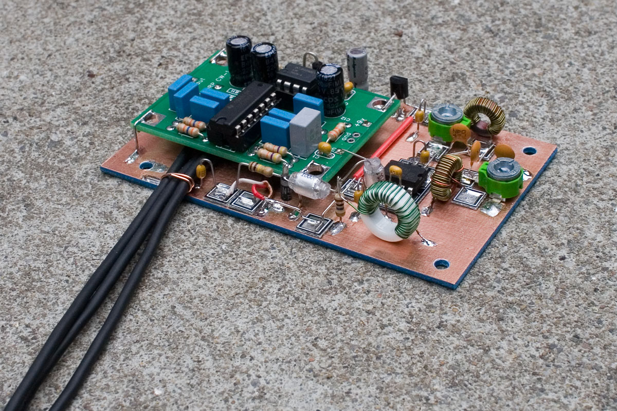
The next step was to build the direct conversion receiver with the NE602 and some of W1REX’s MePADS and MeSQUARES. The most frequency-sensitive part of the VFO circuit was built ugly-style, with the help of a 10M resistor for a stand-off, to help the stability. I don’t have any pictures of the board without the Hi-Per-Mite audio filter/amp added, so here’s the finished board. In the earlier shots, you can see the VFO toroid before I decided to slather it in hot glue in a bid to make it a bit more stable. There is only one component in the final receiver that I missed from the schematic, and that is a 1N4001 diode in series with the 12V supply for reverse-voltage protection. I’ve blown too many fuses in my shack supply to not use these little fellows in the future 🙂

Another shot from basically the same end of the board, showing the input bandpass filter on the left, VFO toroid on the left at the back and the DC input circuit nearest you on the right (reading from right to left, you see the reverse-polarity protection diode, 10uF input smoothing capacitor, 78L08 voltage regulator, and the 0.1uF DC output bypass capacitor. I’ve had those green trimcaps for a long time and it was time they were used. They don’t take solder well (I think I got them from Radio Shack about 10-15 years ago) but it seemed a shame not to use them in something:

Here you can see the varactor tuning circuit built ugly-style just to the left of the VFO toroid. The 3 connecting cables are for the AF gain pot (which is connected in place of R11 and R12 in the Hi-Per-Mite, as per the Hi-Per-Mite instructions), multi-turn tuning pot, and AF output jack. I’ve used lavalier mic cable that I bought from a local pro-audio store. It has 2 inner conductors shielded by a single outer braid and is very flexible, which makes it useful for wiring up small radios. RF connections (which you’ll see in later photos) will be made with Belden 8216 coax:
At this point, I was very gratified to discover that the receiver actually worked, and seemed to work quite well too. That fact gave me enough inspiration to start building an enclosure to house it in. The next shot isn’t ideal, as the back of the case is a little out of focus. You’ll notice that the front, and the two bolts sticking up on the right side are in focus, but the back of the case (and especially the bolt at the back left) isn’t. When I realized this, I was too far along installing the board to go back and take another shot and besides, sometimes I just have to control myself and keep forging ahead:

A view of the board installed in the case, with the lid:

A closer view from the top, in which you can see the VFO toroid now doused thoroughly in hot glue. I’m not sure if it helped the long-term stability at all, though it did help to make the VFO more resistant to physical shock. Another way of securing the VFO toroid in a vertical position would have been to drill 2 small holes in the PCB and use a small nylon tie:

The coax that leads from the 1K log RF attenuator pot to the board is a little long, and that is because the one you see in the photos is a 10K linear pot. It was all I had at the time of building. I am going to swap it out for a 1K log pot when the next order arrives from Mouser in a few days, and kept that lead a little long in case I need to chop some of the end off when changing the pot out.
Here’s another view of the innards. I am quite pleased with the way this little receiver turned out. You can see one of the 4 brass nuts that are used to secure the lid to the rest of the case. I use brass, as I can solder to it with regular solder. When placing the nut, and before soldering, I screw the 4-40 machine screw through the side of the case into it so I know the nut is in the right place. If I were to get a little over-zealous when applying solder and accidentally get solder on the screw it wouldn’t stick, as the screw is made of stainless steel:

This is what The Rugster looks like in her case with the lid on:


If you look closely at these pictures, you’ll see that the PCB panels don’t line up perfectly and that the edges are just a little rough. I am somewhat detail-oriented, but I am not a craftsman by any means, and I know my limits. I made a conscious decision not to spend a lot of time filing and sanding edges. After making deep scores in the board and breaking it, I ran the edges across a file on the bench a few times and left it at that. Good enough is good enough in this case, and it’s certainly good enough for me.


A view of the underside:

I’ve spent a few evenings listening to it and most of the signals that my K2 could hear, this little receiver could hear almost as well. With the very weak signals the K2 won, of course. A small part of this could be due to the fact that the DC receiver, even with it’s 200Hz-wide filter, is still at a 3dB disadvantage to a single-signal receiver (such as a superhet), as it is hearing on both sides of the local oscillator. Naturally, I expected my K2 to be the better receiver (duh!) but was really surprised at what an enjoyable experience listening to this one is for such a simple circuit. As expected, it does overload in the evenings, but all I have to do to get rid of the breakthrough is to adjust the RF attenuation pot back a little from “full gain”, and the breakthrough disappears. Elecraft use an NE602 in the front end of the K1, and it has an attenuator for the same purpose. I’m not sure whether the breakthrough is from strong in-band amateur signals or from AM broadcasters – it’s actually hard to hear the content due to the narrow bandwidth of the Hi-Per-Mite. One small adjustment of the RF gain pot and it’s gone – then I just bump up the AF gain a bit to compensate. Volume is enough to drive my MFJ-281 ClearTone speaker. I normally like to listen to CW with a 500Hz note, but because the response of the ClearTone drops off below 600Hz, I kept the Hi-Per-Mite filter at it’s design center-frequency of 700Hz, and the speaker sounds good. EDIT – If the AM breakthrough is from signals in the 550 – 1700KHz AM broadcast band, which I strongly suspect that it is, a simple high-pass filter with the cut-off set somewhere around 2 or 3MHz should work wonders to eliminate this.
Another point I wanted to mention is that even though the Hi Per Mite employs an LM386 for the AF amp, it is used in the low-gain configuration. Because of this, you don’t hear any of the hiss that is heard in other simple receivers that employ a 10uF capacitor between pins 1 and 8 for high gain. This is a surprisingly pleasant receiver to listen to.
The fact that the tuning rate is quite low helps a lot in the enjoyment of this receiver too. The 10-turn pot covers 6999KHz – 7051KHz giving an average tuning rate of about 5KHz/rotation. The VFO shifts in frequency very little indeed when the receiver is knocked or moved. Drift is not great, but manageable. Drift in the first 10-15 minutes is only slightly worse than after that initial warm-up period, so I’ll give you the results from switch-on, which were 90Hz drift in the first hour, 140Hz drift in the second hour, and 110Hz in the 3rd hour. All the drift was downward – there was no upward drift at all. The drift was steady, and with a little bit of compensation, I think those figures could be improved upon quite a bit. However, for casual listening (and this is all I am going to use this for) it is adequate.
This receiver is certainly not perfect, but considering it’s just an NE602 and an LM386 (oh – and a quad op-amp IC for the filtering), it’s not bad at all.
Thanks Dave NM0S and 4SQRP for this neat little audio CW filter kit.
Here are a couple of videos that I just made of The Rugster. Please excuse the poor video quality – it’s an old, cheap camera:
This one is a little shorter:

Well done, OM!! Yes, 4SQRP kits/boards are the best! These guys are filling a void. I have a few of the AA0ZZ keyers in Altoids tins, and a Pixie II 40M transceiver in a tin.
Excellent stuff, and the video is wonderful!
72/72, Steve WB4OMM
Dave, nice little RX indeed! I’d like to build one like that too, but I’d use a separate VXO to feed pin #7 of the NE602. Can you tell me the RF voltage that you have on that pin with your implementation? If you can take that trouble I’d be most grateful! Tks es 72/73 de Carlo/IZ4KBS
Carlo – it will take me a few days to get round to measuring that RF voltage for you Carlo. I have a bunch of things going on here. Will do my best.
Dave, thank-you for your immediate reply! No problem with waiting, it will take even more days before I actually start building the thing, so it wasn’t meant to be urgent! Agn mni tks es 72/73 de Carlo/IZ4KBS
Quick thought Carlo – why use a separate VXO? Why not use the internal oscillator of the NE602 and use a crystal and variable capacitor in place of the usual LC tuned circuit?
Dave, okay, then I’ll leak my plan 🙂 I’m thinking to couple your simple RX with an NS-40 TX to make a complete (albeit unusual) RTX for portable use, somewhat similar in spirit to the old WWII Paraset, but using modern (and much more power-savvy) components. Obviously, the VXO is going to be 4SQRP’s SAVXO 😉 The alternative would be to build your RX as-is, and use fixed XTALs with the NS-40, which would be more Paraset-like, at the expense of frequency agility and ease of zero-beating between the RX and the TX. Of course hard-core “Parasetters” would trow stones at me if they read this 😛
Regarding my original request, after some more Googling I’ve found all the answers I was looking for, which will save you the trouble of probing through your rig’s guts. If an external oscillator is used, the signal must be injected into pin #6 of the SA602, with pin #7 left unconnected (or used for frequency readout). The RF voltage from the external oscillator should be 200-300 mVp-p.
Dave, looking at your hand-drawn schematic I seem to read T37-7 for the VXO toroid. Is that correct? Did you choose a type-7 core for any particular reason, over the more common type-2 that you used for the two toroids in the bandpass filter? Thanks, de Carlo
Again, I answered myself: http://www.qrp.pops.net/VFO-2011.asp . It looks like that type #6 cores (which I have in quantity) should fit the bill equally well (unless you tell me otherwise).
That’s actually a T50-7 core Carlo and it looks as if you found the answer from Todd’s very excellent site. The type 7 cores are a bit more temperature-stable than the type 2 cores, hence their greater suitability for VFO inductors. It’s probably not as critical with a VXO inductor. Although the type 7 cores are just a little bit more temperature-stable than the 6’s, the difference is minimal. If you have plenty of the type 6 cores, I’d use those.
While you’re browsing Todd’s site, he has done some recent work on input bandpass filters for NE602-based receivers which are directly applicable here. Look on the page http://www.qrp.pops.net/bp-fil.asp – about 2/3 of the way down under the headg “QRP — Posdata for August 2012 — NE612 Mixer Band-pass Filters”.
Dave, yes, I keep making silly typos, like writing T37 instead of T50, and SA602 instead of NE602. I tend to spot them only after I’ve pressed the “Post message” button, too late
Thank-you for the excellent pointer to designing input bandpass filters. Do you think it may be worth using one of those over your simpler solution? The Hi-Per-Mite is already quite narrow of its own, so I thought I could do away with a simplified input filter, like you did. There are simple NE602 based rigs, like the SST, that do not even have any input bandpass filter and rely solely on the IF crystal filter coming after the NE602 RX mixer. Yes, an IF filter may be more effective than an audio one, but I think that’s especially true if the rig as some form of AGC, to avoid strong interfering stations from “pumping” the AGC over the weaker ones, what you think ? If you think that an improved bandpass filter can be preferable, then I’ve already got a couple of these:
http://kitsandparts.com/univbpfilter.php
I used one of them in my VRX-1 DC receiver with great results, but the stock VRX-1 audio filter is nothing like the Hi-Per-Mite.
Carlo – Todd’s BPF’s are no more complex than the one in my RX, which was fashioned after the input filter on the Sudden Receiver, but Todd’s filters are designed to match into the higher input impedance of the NE602/SA612. Whether that will make a difference in practice I don’t know. I don’t think Todd does either (we did talk a little about this.)
After using the RX for a while, I have 2 main thoughts on it. The first is that while the Hi-Per-Mite is a good filter, the 200Hz b/w is a little narrow for everyday listening. That’s just my preference of course, but I prefer to tune around and do general listening with a wider b/w, switching to a narrower b/w if and when necessary. The other thing I noticed was occasional breakthrough in the evening from what I think was in-band AM broadcast stations. I didn’t always immediately notice it, as the filter is so narrow, it doesn’t pass speech very well. Usually, attenuating the input signal with the 1K pot in the antenna input circuit got rid of the breakthrough but I would prefer not to have to deal with it at all.
I built this RX out of curiosity, to see what a simple NE602-based direct conversion receiver with a very narrow audio filter would sound like. It does sound fairly good but for a little more circuit complexity, you could use an ADE-1 DBM (or similar) in your receiver and get much better dynamic range. For low battery consumption portable gear, this circuit does the job though.
Dave, thank you for the wealth of info. Yes, I’d imagine that 200Hz is a bit narrow for band scanning and general listening. One option is to add a switch that bypasses the op-amp filtering stages of the Hi-Per-Mite by means of a simpler L/C filter like the one used in most DC receivers, but I wonder whether that may reduce the advertised 50 dB gain of the filter. What you think ? Do those op-amps contribute to the total gain, or is it provided solely by the LM386? Regarding the occasional BCI, I do not believe they will be more severe than what they are with the SST, the SW+, the PFR-3, and other simple NE602/SA612 designs. Thank-you for your continued availability.
The op-amps do provide some of the gain of the Hi-Per-Mite Carlo. Pins 1 and 8 of the LM386 are not connected, meaning that the internal 1.35K resistor sets the gain at 26dB. Sorry – it’s early here and I just woke up, so I don’t have any other thoughts right now!
Good morning Dave, I wish you had a nice and relaxing breakfast, that’s a great way to start the day 🙂 Back to the filter, I’m starting to think I may be better off using a NEscaf, which already sports a variable b/w. I’ve got one unbuilt here, and I have already built other units in the past, so I know they work well, though they may be slightly less easy on the battery than the Hi-Per-Mite. It’s 5:17pm here now, still plenty of time to think about it. Heck, I may even build that NEscaf by dinner time! 🙂
Dave, the pictures appear to be “broke” on this page. Please fix — I need to see what you’ve done here!
Are you planning on going to Ozarkcon this year? We need an eyeball QSO sometime.
KB9JLO
Dan – I just had a friend pull up this post on her computer and the pictures are loading fine for her, as they are for me, so I don’t know what is going on. Everything seems to be fine at this end. Maybe if you try again later it will work. You know, I haven’t been to a hamfest in over 25 years. I don’t have any plans for OzarkCon I’m afraid. Even my friends comment on how hard it is to get me to go anywhere – I’m a bit of a recluse, to be honest. Maybe some day. I hope you’re able to load this post with all the pictures soon – let me know how that goes.
I figured it out. You’re hosting your pictures at pbase.com — and somewhere along the way they’ve gotten blacklisted by OpenDNS. I use OpenDNS for filtering, both at work and home. I’ve had almost now virus/malware/spambot, etc… breakouts since I started using them for DNS (they filter at the DNS level). Yes, I’m pretty tight as the administrator just because “breakouts” can be so costly in both time and money. Anyway, solved and I’ve allowed it through so I can see your pics now!
Glad you figured it out Dan. I should have mentioned that I am hosting the pictures at pbase.com. Didn’t think about it. My apologies, but glad you got it sorted out.
I really enjoyed the different kits. I like the idea of the MePads and MeSquares. I wish we had those way back in the 80s when I was in college in electrical engineering. Some times I look at some of the ham radio amp books and think about building one some time. Just want to say excellent information.
What gauge wire did you use on the T50-7?
I don’t remember Jason – it was either 26 or 28 gauge – I’m thinking 26 from looking at the pictures. You probably already know this, but with a toroid, the gauge of wire has minimal effect on the inductance. If the wire you use is too thick, you may not get all the turns you want on the toroid and if it’s too thin, the toroid may not self-support too well. I stick with the range of 22 – 28 gauge for nearly all of my toroids. There are also different trains of thought on the wire gauge to use for maximum frequency stability. Some think that thick wire provides greater stablity but Todd VE7BPO in comments on his site, inspired by W7ZOI, says that there is evidence to suggest that thick wire creates extra air gaps between the wire and the core that degrades stability due to the heating and cooling of the air in the gap. His argument is that thinner wire fits more snugly to the core and minimizes this problem. These discussions are not too relevant with a receiver like this, where there are other factors that have a greater effect on the frequency stability, so I’d use whatever you have in the range of 22 – 28 gauge – 26 sounds about right!
Thanks.
Dave, I don’t know if you still check for comments here but I just noticed your work tonight. I just wanted to say (from a really old radio man) that I think the work you are doing here is wonderful. The art (and science) of hand building radio equipment is almost gone. People like you are keeping it alive and I am very happy to see what you’re doing. Furthermore, from one craftsman to another, your work is not only innovative but beautiful. You did a really nice, dare I say, professional job building this receiver.
Larry Cagle
K4WLO
Thank you Larry. I really appreciate that.
Dave
AA7EE
Thank you Dave, your article inspired me to build a (my first homebrew) receiver.
Hendri
YD1IUK
Hendri – I’m really happy to hear that you’ve built your first receiver. It’s a big step. Congratulations!
Dave
AA7EE